In the electrical wiring of buildings, a cable tray system is used to support insulated electrical cables used for power distribution, control, and communication. Cable trays are used as an alternative to open wiring or electrical conduit systems, and are commonly used for cable management in commercial and industrial construction. They are especially useful in situations. TypesSeveral types of tray are used in different applications. A solid-bottom tray provides the maximum protection to cables, but requires cutting the tray or using fittings to enter or exit cables. A deep, solid enclosure for cables i. Common cable trays are made of galvanized,, aluminum, or glass-fiber reinforced plastic. The material for a given application is chosen based on where it will be used. Galvanized tray may b. Combustible cable jackets may catch on fire and cable fires can thus spread along a cable tray within a structure. This is easily prevented through the use of fire-retardant cable jackets, or coatings applied to i.
[PDF]
An electrical wire from the main power supply connects to the distribution box. Around this box, several circuits are attached. Each circuit has its own. Distribution boxes, also known as electrical distribution boards or panels, are pivotal components in electrical systems, ensuring the safe and organized distribution of electrical power throughout residential, commercial, and industrial environments. It receives power from the main electrical supply and divides it into separate circuits, each. Distribution boxes are an essential part of every home or building's electrical system. These enclosures house wiring connections for various applications such as switches, receptacles, and fixtures as well as transition wires for easy access. It takes the incoming power and safely distributes it to different circuits throughout your building. Whether in a home or an industrial facility, this box keeps your electrical setup organized, functional, and efficient. However, the key to.
[PDF]

In this video, we'll walk you through the process of wiring a home distribution box with a detailed connection diagram. This guide provides step-by-step instructions for connecting a distribution box and highlights key factors to consider during installation. What Is a Distribution Box? A distribution box, also known as an electrical distribution board, is a critical component in electrical systems. Whether you're an electrician or a DIY enthusiast, this guide will help you understand the basics of home electrical distribution. It serves as a central hub for distributing electricity throughout a building, ensuring that power is delivered safely and efficiently to all the required locations. It is usually equipped with circuit breakers, fuses, terminal connectors, and other components. It is mainly used to isolate fault circuits, prevent overload, and ensure the safe operation of. The steps to install a small distribution box include selecting a suitable location, installing the base, placing the distribution box, connecting the wires, and checking for acceptance. Warm reminder: Do not disassemble or modify without experience and professionals. Select location Before.
[PDF]

Testing solar panels is easy with a multimeter! To test the current, simply connect the multimeter to the panel's output. Set it to read DC current. To test voltage, set your multimeter to. A $15 multimeter and 5 minutes of testing can diagnose most solar panel problems. Measure Voc (open circuit voltage) — if it reads 0V, the panel or wiring is dead. If it reads 60–80 % of rated, a bypass diode has failed. If Voc is normal but the system is not producing, the problem is downstream. Solar panels are usually tested under standard conditions using a light source that mimics the light from the sun on a clear day. You can use the following method if you want to test your solar panel under standard conditions. We will cover the. A multimeter is a tool that measures the voltage, current, and resistance of an electrical circuit. Fluke recommends using the Fluke 117 Electrician's Multimeter or Fluke 283 FC CAT III 1500 V Digital Multimeter to test solar modules. This helps you spot issues early and keep your system running efficiently. By the end of this guide, you will be equipped with the knowledge to diagnose.
[PDF]

This video shows real on-site footage of electrical installation, demonstrating safe and standardized wiring methods used by professionals. Let's break it down into two main parts: the outer shell and the electrical parts inside. The enclosure protects the electrical components from water, dust, and damage. When choosing one, check the IP or NEMA rating. A. The ideal location to install electrical distribution boxes should keep a distance from water, flammable and explosive substances and corrosive substances. If they need to be placed outdoors, especially in high humidity, you must ensure their waterproofness. Below is a quick checklist of everything you will need for a safe and efficient installation: Connecting a distribution box involves several steps to ensure proper electrical flow. Follow this guide. Box installation: Make sure that Distribution box has been correctly installed and fixed. Material preparation: Prepare the required circuit breakers, wires, wiring ties and other materials, and ensure that they meet the design drawings and installation requirements. Location determination:. Understanding the wiring diagram of an electrical panel box is essential for electricians and homeowners alike, as it allows them to troubleshoot any electrical issues, carry out repairs, or make additions to the system. The electrical panel box wiring diagram provides a visual representation of.
[PDF]
In this video, we'll walk you through the process of wiring a home distribution box with a detailed connection diagram. Whether you're an electrician or a DIY enthusiast, this guide will help you understand the basics of home electrical distribution. more Welcome to our channel! In this video. This guide provides step-by-step instructions for connecting a distribution box and highlights key factors to consider during installation. What Is a Distribution Box? A distribution box, also known as an electrical distribution board, is a critical component in electrical systems. It takes the incoming power and safely distributes it to different circuits throughout your building. However, the key to. A junction box provides a necessary protective enclosure for all electrical wire splices and connections, which must never be left exposed within a wall or ceiling. It serves as a central hub for distributing electricity throughout a building, ensuring that power is delivered safely and efficiently to all the required locations.
[PDF]

In this video, we'll walk you through the process of wiring a home distribution box with a detailed connection diagram. Whether you're an electrician or a DIY enthusiast, this guide will help you understand the basics of home electrical distribution. more Welcome to our channel! In this video. A distribution box is the heart of any electrical system. It takes the incoming power and safely distributes it to different circuits throughout your building. However, the key to. Material preparation: Prepare the required circuit breakers, wires, wiring ties and other materials, and ensure that they meet the design drawings and installation requirements. Location determination: Determine the installation position of the circuit breaker according to the position of the. In modern electrical systems, cable distribution boxes (also known as electrical distribution boxes or distribution boxes) play a crucial role as the key hub for managing, distributing, and protecting circuits. Whether it is residential buildings, commercial facilities or industrial sites, the. Hey, in this article we are going to see the Single Phase Distribution Box Wiring Diagram and Connection Procedure. A distribution board or distribution box is where the main power supply is distributed to multiple loads.
[PDF]

This video shows real on-site footage of electrical installation, demonstrating safe and standardized wiring methods used by professionals. But first, the rules: Turn off the power when working with electricity. Make sure the power's off using a non-contact voltage tester or multimeter. One final tip: Get into the habit of making connections in this. How to make proper & safe electrical wiring splices & connections: This article answers basic questions about how splices (connections between two or more electrical wires) are made to connect & secure electrical wires together in residential or commercial building electrical wiring systems. We. There must be a simpler way to connect the bare wire inside a duplex box. When I run a circuit into a duplex recepticle box, to an outlet, then back out again on to the next box, I wonder how to connect the bare wires together and at the same time, to the recepticle. In the past, I have cut a 6". How to properly bring bare #6 copper into service panel? I've got a small service panel in my shed (6 circuits). I drove 2 8' grounding rods outside and have routed continuous #6 bare copper into the shed. What kind of. Before installation, it's important to know what makes up a distribution box. Let's break it down into two main parts: the outer shell and the electrical parts inside. The enclosure protects the electrical components from water, dust, and damage. When choosing one, check the IP or NEMA rating.
[PDF]

Electrical clearances are the minimum separation distances the National Electrical Code (NEC) requires between wiring, panels, overhead conductors, and everything around them. These rules exist to prevent electrocution, fire, and equipment damage. Dedicated space: The space equal to the width and depth of electrical equipment in addition to the space extending. However, a common question arises: how many wires can you safely put in an electrical box? The answer might surprise you, as it's not just a simple number. In this comprehensive guide, we'll delve into the factors that determine the maximum number of wires, the risks of overcrowding, and provide. The National Electrical Code (NEC) governs electrical junction box rules. These rules define when you must install a box, how large it must be, how you must install it, and how inspectors evaluate compliance. This guide breaks down the actual rules inspectors check — with calculations and. Mandatory separation distances between electrical components and gas lines are governed by national and local codes prioritizing public safety. These regulations minimize potential hazards that arise when the two utility systems are in close proximity during new construction or renovation. Adhering. Electrical panel clearance is a critical aspect of workplace safety, ensuring that electrical equipment is accessible and maintainable without risk of injury.
[PDF]
This comprehensive guide investigates the most frequent wire management challenges faced in real-world setups and demonstrates how the correct cable tray accessories may address them. Steel cable trays form the backbone of organized and efficient electrical wiring in industrial, commercial and infrastructure projects. Whether installed as stainless steel cable trays, these components offer durable and flexible solutions for routing cables safely. However, errors during the installation process can compromise the performance and durability of the trays. It also offers future-ready ideas, troubleshooting guidance, and useful suggestions to guarantee your cable systems. Cable trays are an essential part of electrical installations in buildings, providing support and protection for various cables and wires. However, like any other infrastructure, cable trays are prone to failures that can result in serious safety hazards, financial losses, and downtime. It is a safe way to route cables for easy maintenance and future upgrades. According to the 2005 National Electrical Code® (NEC), a cable tray system is " unit or assembly of units or sections and associated fittings forming a structural system used to securely fasten or support cables and raceways. " Cable trays support cable across open spans in the same manner that.
[PDF]

Learn how to connect equipment grounding conductors to receptacles and keep their continuity in boxes. Sometimes if I have a 3 or 4-gang plastic nail-on switch box that has a bunch of NM cables, when I'm making up the box rather than using a big blue wire-nut for my grounds I'll separate the grounds into 2 groups and use red/tan wirenuts instead, especially if there's 2 circuits in the box. I can. In a metal box, a wire type equipment grounding conductor can be attached to the box with a ground screw or clip and terminated to the switch or receptacle in the box. Connecting the receptacle grounding terminal to the metal box ensures an effective ground-fault current path. The basic rule achieves this through an equipment grounding jumper; four exceptions. I'm using metal box has two ground screws, can I wrap around one ground wire (from supply side) on one of ground screws then connect it to the outlet and connect another ground wire (or two wires ) going to the next box (es) on the secondary ground screw? I know pig-tail method is probably better. Electrical boxes play a crucial role in housing and protecting electrical connections, ensuring safety and functionality. Among the various types of wires found in an electrical box, the ground wire is of paramount importance. It provides a path for electricity to safely flow to the ground.
[PDF]

To connect a router to a switch, simply plug an Ethernet cable into one of the router's LAN ports and connect the other end to any port on the switch. This creates a seamless network where multiple devices can share the internet connection and communicate efficiently. What is the best method to use when connecting a router to your core switch? Should I put the switch port in a vlan where the IP of the router interface is or should the port not be a switchport and give it an IP? I know both methods will work but I want to know what is the better method to use. Here is what you can do by connecting a switch to your router: Increase the available number of Ethernet ports and improve network efficiency by eliminating Wi-Fi congestion. Optimize how you set up your networking infrastructure. This configuration is great when you have lots of devices that need. While a wireless router is fine for most users, a network switch provides additional ethernet ports for wired devices. Whether you are setting up a small home network or a large-scale enterprise network, understanding how to connect these essential networking devices is crucial. Switches are responsible for transferring data within a LAN, while routers are responsible for transferring data between different networks. In this blog, we'll provide a step-by-step guide to help you achieve it.
[PDF]

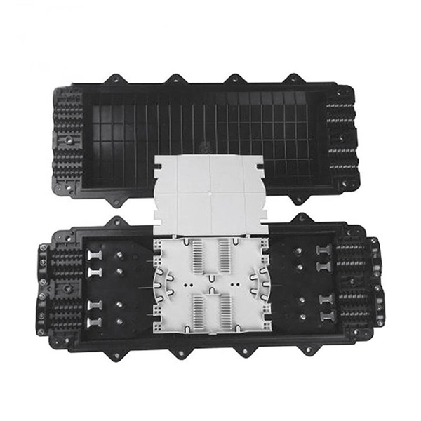
This complete guide explores everything you need to know about ODFs — from their structure, types, and key components, to installation best practices and modern design trends. A fiber optic distribution box, also known as a fiber optic terminal box or termination box, is a device used to connect and manage fiber optic cables within a network. It acts as a central point for terminating, splicing, and distributing these cables, providing necessary protection and. Fiber distribution boxes play a crucial role in network management, providing a centralized and protected access point for optical cables. Distribution boxes are especially essential for FTTH networks, where they enable the efficient connection and management of optical fibers from a central. Fiber distribution boxes represent a critical component in modern telecommunications infrastructure, serving as the connection point between main fiber optic cables and individual subscribers. It is primarily used to terminate, splice, and organize optical fibers, providing a structured cabling solution for in-building and outside plant applications.
[PDF]
