There are many ways to build and deploy fiber optic cables and each has pros and cons when considering cost, speed, safety, and complexity. This white paper focuses on the emergence of microtrenching – why it has become so prevalent and the many benefits it brings. From walk behinds to ride-ons, Ditch Witch trenchers are the world standard. 4 mm) digging depth for efficient installation of pipe and cable, the C16X is all about reliability and productivity. A compact design combined with a reliable 24-hp (17. 9-kW) Honda® engine, the C24X will. Tesmec offers an integrated value chain with specialized solutions: underground utilities detection and mapping, trenching, vacuum, home connection, backfilling, and road surface finishing. Tesmec trenchers are used for the installation of underground conduits for telecommunication networks. We. Hot Sale Fiber Optic Trenching Machine - Automatic Chain Trencher for Efficient Trench Digging, 15-25cm Working Width. The self-propelled chain trencher adopts a chain belt scraper structure, which can dig trenches and grooving operations on any type of soil. The self-propelled chain trencher can. THE SOLID APPROACH TO TRENCHING. The Plastibeton® cable trench is a trusted system by power, utility, railroad and transit companies throughout North America to contain, protect and allow easy access to power, control, signal, communication, and fiber optic cables.
[PDF]

Instead of being hardwired to accept only one type of cable, an SFP+ port accepts small, hot-swappable modules—called transceivers—that you simply slide in and click into place. Need a fiber connection? Pop in a fiber module. Prefer copper? There's a module for that too. A fiber optic transceiver (also called an optical transceiver) is a compact module that both transmits and receives data signals through optical fibers. It serves a dual purpose — transmitting electrical signals as light pulses and receiving light pulses to convert them back into electrical form. An SFP transceiver acts as a compact, hot-swappable optical transceiver that. When building or upgrading a network, many IT managers focus on switches, routers, and access points—while overlooking one critical piece of the puzzle: the optical transceiver. These small modules determine how your uplinks operate: the speed, the distance supported, and whether your Cisco or. Fiber optic cabling is an alternative to copper cabling for data transmission. Popular options include: LC: Common on SFP, SFP+, XFP, QSFP, and SFF transceivers. ST, MT-RJ, and MPO: A bit less common but still in use.
[PDF]

Will fiber optic cables replace coaxial cables entirely? The short answer is: not entirely. In this article, we'll help you understand where each. Fiber optic cables and coaxial cables have something in common; both of them can provide homes and businesses with tv, phone, and Internet service. Cables. Optical fiber can carry analog RF signals from antenna to receiver with far less loss than coaxial cables. It's not unusual in engineering to find solutions to long-standing problems leveraging apparently unrelated technologies. But these signals have a fatal flaw: when transmitted through traditional copper coaxial cables, they degrade and distort rapidly over distance. It's like shouting into a long metal pipe—the sound that comes out the other. Seamless Radio Frequency Signal Transmission over Optical Networks RF over Fiber (RFoF) technology enables the transmission of radio frequency (RF) signals over optical fiber instead of traditional coaxial cables. This method combines the advantages of fiber optics—such as low signal attenuation.
[PDF]
Fiber Optics Market was valued at USD 8. 1 billion in 2023 and is anticipated to grow at a CAGR of over 5% between 2024 and 2032. The demand for high-speed broadband access is accelerating with end-users increasingly seeking high-quality multi-gigabit services to power their homes and. Fiber Optics Market was valued at USD 8. Cartesian received input to this study from across the industry and nation. Respondents spanned the fiber construction ecosystem from. Market Size by Fiber Type (Glass Fibers, Plastic Optical Fibers), by Cable Type (Single-mode, Multi-Mode), by Deployment (Underground, Aerial, Underwater) by End User & Forecast. 8 billion by 2029 from USD 3. 4% from 2024 to 2029. Rapid expansion of data centers, cloud services, and 5G infrastructure is driving strong adoption of fiber optic solutions. The global deployment of 5G networks by telecommunications.
[PDF]
A fiber optic switch allows optical signals to be selectively switched from one fiber to another, while a fiber optic splitter divides an optical signal into multiple signals, allowing it to be transmitted to multiple devices. It is essentially a switch that operates at the optical layer of a network, rather than at the electrical layer. Conversely, it can also combine multiple signals into one. Its primary role is in Passive Optical Networks (PON), which are the foundation of. A fiber optic splitter is a passive optical component that divides a single incoming optical signal into two or more outgoing signals, or combines multiple incoming signals into one. The optical network system uses an optical signal coupled to the branch distribution. The fiber optic. While the splitter doesn't manage or direct traffic like a switch, it does allow multiple devices to access the same network connection. The devices connected to the splitter typically need to be configured to work with the shared connection, and bandwidth may be divided among the devices based on. A passive device used to split or combine signals on fiber optics may be called a splitter, combiner or coupler, but splitter is the most common term. They have been used since the 1980s to create networks and provide the technology for today's passive optical networks used in fiber to the home.
[PDF]
Search results of Top 2 Cabling and Fibre Optics Companies in Malawi, near me. Listings are verified with accurate business information. The Optic Fibre Communications (OFC) is a semi-autonomous department within ESCOM that operates a national wide overhead Optic Fibre backbone network strung on electricity infrastructure reaching all parts of the country and the National Data Centre supported by the Malawi Government. This gives. Fibre Optic Networking Solutions, established in 2011 in Malawi, specializes in cutting-edge fibre optic networking solutions, internet broadband infrastructure, connectivity, fiber installation, and comprehensive network services. Custom telecommunications tower design, construction and maintenance. Looking to buy a Gratings in Malawi? Jeetmull Jaichandlall (P) Ltd. is one of the trustworthy Gratings Manufacturers in Malawi that is here to fulfill all your wire mesh and netting tools needs. Every buyer chooses us first because of our. Fibre Optic Networking Solutions is a Malawian company. The company was fully registered in Malawi in August 2011. The company is committed to play a major role in providing best fibre solutions to meet future demands in high-capacity data transmission. Last updated Apr 2026 Unlock the full database with advanced filters and visible emails inside Data Hub — Free Trial available.
[PDF]

Panjiva uses over 30 international data sources to help you find qualified vendors of Ecuadorian sensors. Get access to all 13 remaining Fiber optic products suppliers with complete contact information, addresses, and business details. As of May, 2026, we have compiled data. Pricing (USD) Filter the results in the table by unit price based on your quantity. Fiber Optic Sensors are available at Mouser Electronics. Mouser offers inventory, pricing, & datasheets for Fiber Optic Sensors. How does 6Wresearch market report help businesses in making strategic decisions? 6Wresearch actively monitors the Ecuador Distributed Fiber Optic Sensor Oil & Gas Market and publishes its comprehensive annual report, highlighting emerging trends, growth drivers, revenue analysis, and forecast. These results have not been confirmed by Panjiva and are provided on an "AS IS" basis, as further described in Panjiva's Terms and Conditions of Use and Panjiva's Transparency Policy. Your use of the information provided in these results is subject in all respects to those Terms and Conditions of. Furthermore, the expansion of smart cities and the adoption of the Internet of Things (IoT) are amplifying the demand for distributed fiber optic sensors. 7 million in 2024 and is projected to grow from USD 1,581.
[PDF]
Unlike, single-mode fiber does not exhibit. This is due to the fiber having such a small cross section that only the first mode is transported. Single-mode fibers are therefore better at retaining the fidelity of each light pulse over longer distances than multi-mode fibers. For these reasons, single-mode fibers can have a higher than multi-mode fibers. Equipment for single-mod.
[PDF]

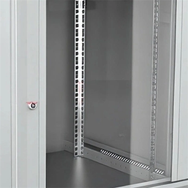
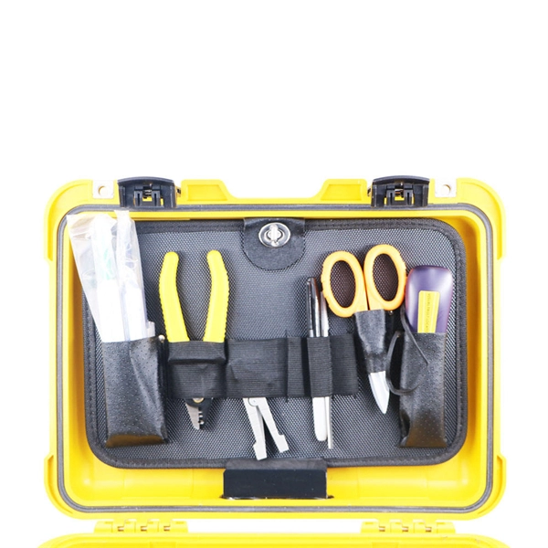
Extending the fiber through the box makes use of a cable entry gland. Fasten the cable to the clamps or ties to assure the cable is immovable. Cable must be properly minimum radius (usually ≥30mm for standard fiber). Remove the cable jacket and buffer coating material. Thus, a fiber termination box is used to terminate the optical fiber cables in the field and connect them to the pigtail by splicing. After an optical cable arrives at the user's end, it is fixed in the terminal box. Fiber adapters: These are used to connect the fiber optic cables to the fiber termination box and should comply with industry. Teleweaver emphasizes the importance of choosing the right FTB based on specific requirements. The common types include: Wall-Mounted FTBs: Ideal for residential and small-scale applications, these are compact boxes designed to be mounted on walls for easy access and space-saving cable management. To address this problem, the fiber termination box (FTB) was created to protect the fragile fiber terminals and provide a simple and clear way to manage the incoming and outgoing cables. more Order it here: https://www. This video shows you a step-by-step instruction on how to terminate 12 strands single mode fiber cables, splicing them with fiber optic pigtails.
[PDF]
In the single mode vs. multimode fiber debate, there is not one cable that's the best, but there are some that are better suited to certain situations. If you need to run fiber optic cable over a vast distance, there's.
[PDF]

MUSCAT: The Royal Oman Police (ROP) has reported a disruption to internet services in parts of South Al Sharqiyah Governorate after fibre optic cables belonging to a telecommunications provider were accidentally cut during construction work in the Wilayat of Sur. Royal Oman Police say repair work underway; services expected to be restored within hours. ROP said in a statement: "The Royal Oman Police announces a disruption in fiber optic connections belonging to a telecommunications. Microsoft said in a status update that the Middle East "may experience increased latency due to undersea fibre cuts in the Red Sea," but gave no other details. Fibre optic cables on the ocean Floor. File pic: iStock Internet access in parts of Asia and the Middle East was disrupted after undersea. „Oman Fiber Optic always offers great service with quality product. They have very good technical sales team and logistics team and are always available for support. „ „Professional supportive sales team with excellent material quality leading to a great service!„ Technology Integration on time. Sur – Royal Oman Police (ROP) has announced a significant disruption to their digital services within the South Sharqiyah Governorate following an accidental severance of fibre optic cables. The technical failure occurred in the Wilayat of Sur, where ongoing construction activities inadvertently.
[PDF]
This splice case protect fiber optic cables and juction from outside plant environment damage. They are made of reinforced ABS or PC plastic, which has high strength and corrosion resistance. In addition, the splice enclosures are all hermetically sealing structure, waterproof and. Standard polycarbonate (PC) or Glassfibre reinforced (PC+GLAS) PP ABS (Acrylnitrile-butadiene -styrene) Slightly lower UV resistance compared with PC. Recommended for outdoor use if protected against weather influences GRP – GLASS FIBRE REINFORCED POLYESTER Polycarbonate and ABS enclosure materials. The fiber optic splice closure is a closed structure used for splicing, protecting and managing optical fibers. Its material selection is crucial to ensure the quality and service life of the fiber optic splice closure. These boxes are well suited as optical cable splice collection points for DAS (Distributed Antenna Systems), MTU (Multi-Tenant Unit) commercial business applications, and MDU (Multi-Dwelling Unit). It is a reentry box which is made of PC or PP material. The shells and the base are sealed with silicone gum. This product can be re-entered and used again after it is opened. Typically selected for high-density OSP splicing and branching. What is the basic structure of Fiber Optic Splice Closure? The basic structure of Fiber Optic Splice Closure includes the box body, box components, sealing ring, and lock buckle.
[PDF]
Polarization-maintaining fibers work by intentionally introducing a systematic linear birefringence in the fiber, so that there are two well defined polarization modes which propagate along the fiber with very distinct phase velocities. The beat length Lb of such a fiber (for a particular wavelength) is the distance (typically a few millimeters) over which the wave in one mode will experience a. OverviewIn, polarization-maintaining optical fiber (PMF or PM fiber) is a single-mode in which , if properly launched into the fiber, maintains a linear polarization during,. In an ordinary (non-polarization-maintaining) fiber, different polarization modes have the same nominal due to the fiber's circular symmetry. in such a fiber, or bending. Several different designs are used to create birefringence in a fiber. The fiber may be geometrically asymmetric or have a refractive index profile which is asymmetric such as the design using an elliptical as.
[PDF]