High-definition temperature sensing based on the natural Rayleigh backscatter in optical fiber delivers a virtually continuous line of temperature measurements with sub-millimeter spatial resolution. 1. Map temperat.
[PDF]

Equinox blind spot system may show sensor errors or intermittent mirror detection failures. The 'Side Detection Temporarily Unavailable' warning often indicates sensor blockage or malfunction. Check for physical. That “Service ESC” light means your Equinox's Electronic Stability Control system has detected a problem. This is the system that helps keep your car planted and stable when road conditions get dicey, think wet pavement, sharp turns, or icy highways. When it's not working properly, you lose that. I was leaving an event this evening, and as I was stuck in bumper to bumper traffic my car popped up with a message in the display that the Side Detection System was unavailable (2018 Chevy Equinox Premier). And sure enough, the blind spot detection stopped working. Of course this had to happen at. The time now is 12:49 PM. 2025 chevrolet equinox Technical Service Bulletins (TSBs). These sensors may be dirty, obstructed, or experiencing communication problems. track control etc plus random service messages. 1 click faint light on then off. happened all of a sudden. seems to run ok when it. This sub-reddit is dedicated to everything related to Chevy vehicles: driving, racing, collecting, and more. Equinox Blind Spot Sensors - Where are they? Hi! I just bought an equinox 4 days ago, and suddenly my blind spot warning lights in my side mirrors are coming on all the time when there.
[PDF]

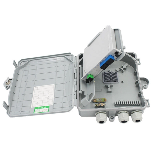
Fiber-optic communication is a form of optical communication for transmitting information from one place to another by sending pulses of infrared or visible light through an optical fiber. The light is a form of carrier wave that is modulated to carry information. Fiber is preferred. This method encodes data into light signals by modulating properties like wavelength, phase, and polarization. The light signals propagate to the receiver through the fiber optic cable. Optical fiber communication relies on the properties of light from the electromagnetic spectrum. By optimizing. These strands, known as fibre optic cables, have revolutionised telecommunications because they transmit information using pulses of light. Unlike copper wires, which send electrical signals and suffer from resistance and interference, fibre optics offer orders of magnitude more bandwidth and. Optical Fiber Light Transmission commonly known as fiber optics is a technology that utilizes thin transparent fibers made of glass or plastic to transmit data and information using the light signals. This technology forms the backbone of global data transfer due to the immense bandwidth capacity of light. Light waves possess a frequency spectrum vastly wider than. Less costly per meter. Lower transmitter launching power. Less susceptible to electromagnetic interference. Flexible use in mechanical and medical imaging systems. Automotive and many other industories.
[PDF]

The setting value can be finely adjusted manually. Press and hold the and buttons simultaneously for three seconds. Use the to select "rSt", then press the button. Settings are summarized in "Basic" and "Advanced" categories. Providing quick solutions for every scenario. In cases where more advanced features or troubleshooting is necessary, the "Advanced". This video covers how to setup and configure the Wenglor OPT2041 Fiber Optic Sensor from AutomationDirect. **Please check our website for our most up-to-date product pricing and availability. This sensor works with both Plastic and Glass fibers. Keep in mind that the color and reflectivity of the. The KEYENCE FS-N10 Fiber Sensor is a versatile and reliable device used for detecting objects. This sensor uses a fiber optic cable to transmit and receive light, allowing for accurate and precise detection in a variety of applications. The FS-N10 series is capable of detecting objects of different. Fiber optic Sensors; How to program Keyence Fiber optics amplifier from EMI Documentation can be found here:. This is the SET push button; this is used to calibrate the sensitivity.
[PDF]

Identify and compare relevant B2B manufacturers, suppliers and retailers. Identify and compare relevant B2B manufacturers, suppliers and retailers. Identify and compare relevant B2B manufacturers, suppliers and retailers Max. Brolis Sensor Technology specializes in advanced photonic sensor technologies, including the development of integrated optical sensors for healthcare and industrial applications. Their innovative sensors utilize. Fiber Optic Devices Ltd. (FOD), an employee owned company, is a complete fiber optic technology company offering a variety of products and services to the OEM and End-user markets. Founded in 1991, FOD is a recognized leader in partnerships in the design and manufacturing of Fiber Optic Components. Also, please take a look at the list of 38 optical sensor manufacturers and their company rankings. Here are the top-ranked optical sensor companies as of May, 2026: 1. WIN SOURCE ELECTRONICS, 2. Vishay Intertechnology, Inc. The Workshop of Photonics (WOP) specializes in femtosecond laser micromachining, providing ultra-high precision services for various materials, including glass and ceramics. Their innovative approach enhances productivity and provides critical data for improving nutrition and.
[PDF]
We describe a theoretical and experimental study of an intensity-based, dual-wavelength referenced fiber optic temperature sensor utilizing temperature-induced spectral shifts of optical thin-film interference coatings, deposited on a sensor fiber end. We present coating design considerations that. This study proposes the development of a dual-wavelength optical fiber sensor (DWOFS) that integrates two optical fiber structures in a multimode transmission line to measure the refractive index and temperature of a liquid concurrently. One structure is based on a refractive index sensor that. ter. The dual-wavelength fiber laser has a ring cavity composed of two FBGs with central wavelengths of 1550. Through monitoring the wavelength shift and the output power difference of the dual-wavelength fiber laser, the simultaneous measurement for RI and temperature is. To improve the sensitivity measurement of temperature sensors, a fiber optic temperature sensor structure based on the harmonic Vernier effect with two parallel fiber Sagnac interferometers (FSIs) is designed, and theoretical analysis and experimental testing are conducted. The FSI consisting of. Fiber-optic high-temperature sensors are gradually replacing traditional electronic sensors due to their small size, resistance to electromagnetic interference, remote detection, multiplexing, and distributed measurement advantages. This paper reviews the sensing principle, structural design, and.
[PDF]
This paper describes the optimal design of a miniature fiber-optic linear displacement sensor. It is characterized by its ability to measure displacements along a millimetric range with sub-micrometric resolution. The sensor consists of a triangular reflective grating and two. displacement, pressure, temperature and electric field. Recently, high precision fiber displacement sensors have received significant attention for applications ranging from industrial to medical fields that include reverse engineering and micro-assembly (Laurence et al. The design and adaptability of Cleveland Electric Labs linear and rotary displacement sensors provide optimum measurement possibilities for a wide variety of applications. CEL s linear sensor has a travel range from less than 1 inch up to 18 inches with an accuracy of 0. 005 and our rotary sensor.
[PDF]
FiberFin offers products specifically designed for the wide variety of sensor applications that POF is used in. There are three common methods for measuring external forces using plastic optical fiber. Optical fiber sensors have revolutionized the way we measure and monitor various physical and chemical parameters in different industries. These sensors utilize the properties of light to detect changes in the environment, making them highly sensitive and accurate. In this article, we will explore. Fiber Optic Sensors for Plastic Components by Application (Electronic Product, Automobile, Industrial Equipment, Others), by Types (Single-Tube, Double Tube, Multitube), by North America (United States, Canada, Mexico), by South America (Brazil, Argentina, Rest of South America), by Europe (United. While fiber optic cables can be used to connect remote sensors to electronic loggers or signal processors the same way that copper wires can, they can also be used as sensors themselves.
[PDF]
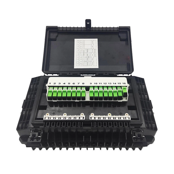
Optical fibers can be used as sensors to measure strain, temperature, pressure and other quantities by modifying a fiber so that the quantity to be measured modulates the intensity, phase, polarization, wavelength or transit time of light in the fiber. Sensors that vary the intensity of light are the simplest, since only a simple source and detector are required. A particularly useful feature of intrinsi. OverviewA fiber-optic sensor is a that uses either as the sensing element ("intrinsic sensors"), or as a means of relaying signals from a remote sensor to the electronics that process the signals ("extrinsic s. Extrinsic fiber-optic sensors use an, normally a one, to transmit light from either a non-fiber optical sensor, or an electronic sensor connected to an optical transmitter. A major benefit of e. It is well-known the propagation of light in optical fiber is confined in the core of the fiber based on the total internal reflection (TIR) principle and near-zero propagation loss within the cladding, which is very important f.
[PDF]

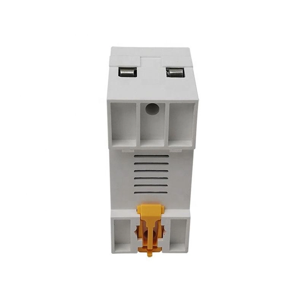
Circuit breaker wiring configurations involve organizing main switches, busbars, and branch breakers within a distribution box. Proper setups ensure balanced electrical loads, ground fault protection, and easy maintenance. Messy distribution boxes are dangerous and very hard to fix. This guide shows you how to organize circuit breaker wiring properly. You will learn to build a safe, efficient, and professional electrical system today. Location determination: Determine the installation position of the circuit breaker according to the position of the. The distribution board is the heart of every electrical installation. This guide covers split load vs dual RCD vs RCBO board configurations, circuit arrangement and allocation, BS 7671 labelling requirements, type testing under BS EN 61439, SPD installation, wiring best practice, and the common. Distribution panels, breaker panels, load center, and/or distribution boards—any name you call them, they're a key part of every electrical system. Wiring distribution panels serve as the central hub and nerve center, routing power from the main service feed to multiple circuits. When setting up. Hey, in this article we are going to see the Single Phase Distribution Box Wiring Diagram and Connection Procedure. It serves as a central hub for distributing electricity throughout a building, ensuring that power is delivered safely and efficiently to all the required locations.
[PDF]

In this guide, learn the basics of reading and interpreting electrical wiring diagrams. Follow Along on SkillCat: "Wiring Diagrams" Course! Want to test your knowledge? Skip to the quiz!. In this article, you'll learn how to read, understand and use a wiring diagram. An electrical wiring diagram could be a single page schematic of how a ceiling fan should be connected to the power source and its remote switches. A wiring diagram may include the wirings of a vehicle. For example, how. Electrical wiring diagrams are an essential tool for electricians, engineers, and automation technicians. Proper interpretation is crucial for understanding the operation of devices, diagnosing faults, and working safely with electrical installations. Understanding how to read electrical diagrams. In order to trace control system problems to the core, the ability to read and interpret various resources, from facility-level diagrams to machine-level wiring layouts, is critical. The engineering world is crammed full of drawings and diagrams of every possible kind. It shields sensitive equipment from dust, moisture, and. After reading and studying this handbook, electricians (or would-be electricians) will have a firm grasp on the many symbols used in electrical diagrams.
[PDF]

There are two electrical terminals, X and Y, where your cables must be connected. In this case, X refers to Black while Y refers to White. You need to connect X and Y with hot and neutral wires respectively. This is the most essential step. Each hot wire is 120 to 240 volts from the. Fortunately, anyone that understands color codes and electrical wiring, in general, can use X and Y wires and terminals. Circuits typically run on three wires. The hot wire brings power from the panel. In a standard setup, X and Y terminals typically correspond to specific colors: black for X and red for Y in 240V systems. Knowing these codes helps you properly connect circuits, ensuring. The standard electrical wire color code mandated by the National Electrical Code (NEC) is a critical safety system for licensed electricians. For typical building AC circuits (commonly up to 600 volts nominal), the NEC specifies identification rules for grounded conductors (neutral), requirements. Wires in electrical typically have color-coded labels., the National Electrical Code (NEC) defines required colors for neutral and grounding conductors, while hot wire colors often follow industry convention rather than strict rules. The table below gives a quick snapshot of the most common electrical wire colors you can see at home.
[PDF]

Mount individual circuit breakers in the designated positions within the distribution box. Each breaker should match the current rating and type required for its specific circuit. Ensure proper connection to the busbars and secure mounting to prevent loosening over time. When opening the distribution box, several different brands of circuit breakers are installed inside. It seems that the sizes match and the installation is fine, and this. The feeder amp rating is sized based on the sum of the amp rating of the largest branch protective device plus the full-load currents of the other loads. This value is added to the full load currents of the. Finding the right circuit breaker for your electrical panel is crucial to ensure safety, performance, and code compliance. Not all breakers are interchangeable across different panel brands – each manufacturer designs its breakers and panels as a matched system. Using a breaker that isn't made or. In industrial power distribution systems, cable distribution boxes (also known as power distributor boxes, distribution electrical boxes, or electrical power distribution boxes) are the core hub of power transmission, branching, and protection. You lower the chance of circuits getting too hot or overloaded when you pick the right box for your needs. A single circuit breaker installation mistake can cost your facility thousands in downtime, equipment damage, or worse—put lives at risk.
[PDF]