
Learn how to install fiber splice trays inside an enclosure step by step. Quick, easy, and essential for fiber pigtail management! https://bit. Unlike fiber connectors, which can be plugged and unplugged, splicing creates a fixed connection that is typically more stable and has lower insertion. This document describes the installation of optical fiber with both single fiber and/or ribbon fiber splices into Optical Splice Enclosure (OSE) metal splice trays (Figure 1). Make sure you read and understand this instruction as well as instructions provided with related assemblies before. By following these detailed steps, the installation of your Fiber Splice Closure will be secure, organized, and maintained, ensuring high performance and longevity of your fiber optic network. Installing a fiber optic splice closure efficiently and effectively requires attention to detail and. How to install the splitter distribution box is the important information we need to know. This article includes the following: 1. Install the fixture 2. Box installation and fixed splitter distribution box 4. Install. Page 5 B (# 7 & 8) enter splice tray # 2. Route the fibers entering the splice tray up to splice point as shown. NOTE : Protection tube from side A enters splice tray from the far end as shown After splicing, close the splice tray and lock the front cover properly with the main and side lock.
[PDF]

- YouTube This kind of box are used in the end termination or residential building sand villas, to fix and splice with pigtails, can be installed on the wall. Thus, a fiber termination box is used to terminate the optical fiber cables in the field and connect them to the pigtail by splicing. After an optical cable arrives at the user's end, it is fixed in the terminal box. Fiber Optic Terminal. Fiber Terminal Box is a terminal protection box for the splicing of fiber optic cable and pigtail. Fiber optic terminal box is a cable end fitting. Modern home networking often relies on a Fiber-to-the-Home (FTTH) connection, which typically terminates at a service provider's external box. Running fiber internally involves extending this high-speed link from the service entry point to a centralized location, such as a dedicated media closet or. This termination box supports 0. 0mm pigtails and 2x3mm indoor drop cables. Furthermore, this fiber termination box's innovative flip-up distribution panel simplifies installation and maintenance, allowing for easy access and efficient handling.
[PDF]

Understanding how to properly place and use an optical splitter is essential for optimizing signal quality and ensuring seamless data transmission. Let's explore the best practices for deploying this crucial component. What is An Optical Splitter?. A fiber optic splitter is a passive optical component that divides a single incoming optical signal into two or more outgoing signals, or combines multiple incoming signals into one. Unlike active devices (which require power), splitters operate without electricity, relying solely on the physics of. Where splitters are placed in the network can make significant impacts on fiber counts, network cost and deployment time and operational steps, such as customer onboarding and maintenance. One important note is that splitting architectures should be seen as tools that can be mixed and matched to. In the realm of optical communication networks, the optical splitter serves a vital role in dividing and distributing optical signals efficiently. You use optical couplers and splitters to split or join signals in fiber networks. These devices help you control light signals well. You can also use them to join light from. This guide will demystify this pivotal passive device, exploring its types, working principles, and how it seamlessly integrates with optical transceivers to bring high-speed internet to your doorstep.
[PDF]

Optical splitters play a crucial role in Fiber to the Home (FTTH) Passive Optical Network (PON) systems, efficiently distributing a single optical signal to multiple destinations. The split ratio and insertion loss are two key parameters defining their performance. Understanding Fiber Optic Splitters: Principles, Parameters, Types, Applications, and Future Trends 1. Introduction Fiber optic splitters are integral components in the world of optical networks. A deeper understanding of these. 📄 What is an Optical Splitter? An Optical Splitter, also known as a beam splitter, is a passive optical device that divides a single input optical signal into two or more output signals. Conversely, it can also combine multiple signals into one. Its primary role is in Passive Optical Networks. Bandwidth is shared amongst customers in a PON, and the bandwidth received by a customer is not related to the power received at the optical network terminal (ONT) as long as the power is high enough so the ONT can operate. Their ability to efficiently manage optical signals makes them indispensable in various. The performance of optical beam splitters can significantly influence the overall performance of laser-based instrumentation and measurement systems. This paper examines two of the most critical performance factors: optical efficiency and wavefront distortion. Efficiency is a function of both the.
[PDF]

By dividing a single optical signal from a central Optical Line Terminal (OLT) into multiple outputs for Optical Network Terminals (ONTs) at users' homes, splitters eliminate the need for dedicated fibers to each residence—slashing infrastructure costs while scaling network reach. High-speed broadband, cloud computing, and 5G communication all rely on one critical passive component: the PLC splitter. As a core device in FTTH and PON networks, a PLC splitter is not just about “splitting light” — it's about delivering stable, low-loss, and uniform optical power distribution at. In the backbone of modern Fiber-to-the-Home (FTTH) networks, optical splitters serve as the unsung heroes that enable cost-efficient connectivity for millions of subscribers. FTTH relies on Passive Optical Network architecture, which enables one fiber leaving the central office. 📄 What is an Optical Splitter? An Optical Splitter, also known as a beam splitter, is a passive optical device that divides a single input optical signal into two or more output signals. Conversely, it can also combine multiple signals into one. Think of it as a prism for modern-day fiber optic communications – directing the light in multiple directions, but without.
[PDF]

Incoming Distribution Cable: The fiber distribution box receives an incoming distribution cable, which typically carries a bundle of optical fibers. These optical fibers originate from a central source, such as a data center, central office, or distribution point. Fiber Distribution Boxes (FDBs) are critical components in modern telecommunications infrastructure, particularly in fiber optic networks. Minimize the interference of the optical cable access signal to the external environment. The. In the complex architecture of fiber optic networks, the Optical Distribution Frame (ODF) serves as the linchpin for organizing, protecting, and distributing optical signals. Whether in data centers, telecom central offices, or enterprise network rooms, ODFs enable efficient fiber management. An optical cable consists of three primary parts: the core, the cladding, and the protective sheath. Surrounding the core is the cladding, which has a lower refractive index than the core. This complete guide explores everything you need to know about ODFs — from their structure, types, and key components, to installation best practices and modern design trends. Whether you're building a central office, data center, or FTTx distribution network, understanding the right ODF.
[PDF]
Its function is to split two incident light beams from two individual input fiber cables into sixty-four light beams and transmit them through sixty-four individual output fiber cables. A fiber-optic splitter, also known as a beam splitter, is based on a quartz substrate of an integrated waveguide optical power distribution device, similar to a coaxial cable transmission system. The optical network system uses an optical signal coupled to the branch distribution. These devices are commonly used in fiber optic networks to distribute signals to various endpoints. Optical splitters work by using a branching mechanism that allows the signal to be evenly. An optical splitter is a crucial passive fiber optic device that splits and combines optical signals. It can distribute the optical energy transmitted through a single fiber to two or more fibers in a predetermined ratio or combine the optical energy from multiple fibers into one fiber. Optical splitter.
[PDF]

This article provides a detailed technical comparison between fiber optic and copper cables, offering a clear perspective for engineers, network architects, and procurement managers. The core distinction between the two technologies lies in the physics of data. However, the exponential growth in data demand has positioned fiber optic technology as the superior alternative for performance, scalability, and future-readiness., 10G/25G/40G/100G and beyond depending on optics and reach). Copper Ethernet scales too, but practical limits are lower and depend. The two main options are fiber optic cables and copper cables, each with its own advantages and drawbacks. Fiber optic cables are praised for their high performance and scalability, while copper cables remain a cost-effective choice, especially for budget-conscious projects and older systems. Copper wire is more susceptible to interference and has limited data capacity, making optical fiber the preferred choice for modern high-speed. Optical connectivity, utilizing fiber-optic technology, has emerged as the superior choice for modern networking, offering unparalleled performance, reliability, and scalability. For example, a typical 10 Gbps copper Ethernet link (such as Cat 6A) over 100 meters can consume approximately 5 to 8+.
[PDF]

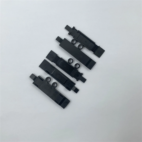
Fiber optic terminal boxes provide functions such as input, branching and splicing of optical fiber cables. Through the connectors and splicing boxes in the terminal box, optical fibers can be quickly connected and repaired. Serving as a critical connection point, FTB facilitates the termination, splicing, or connection of fibers from various cables to other network devices such as switches, routers, or Optical Network Terminals (ONTs). It aids in splicing, splitting, storing, and managing fibers within the appropriate. The optical fiber terminal box is the terminal joint of an optical cable, one end of which is an optical cable, and the other end is a pigtail, which is equivalent to a device that splits an optical cable into a single optical fiber. A fiber pigtail is a specific hardware connection used for cable termination. It is a small enclosure that can house and protect the fiber optic cables, splices, and connectors. The optical fiber termination box and optical fiber splice box serve distinct purposes and are not interchangeable.
[PDF]

First, connect each pre-terminated fiber optic cable to the adapter panel separately, making sure the ports correspond one-to-one; then fix the fiber optic adapter panel to the front panel of the distribution box with the bend radius control clip. In general, installing the optical fiber distribution box can be divided into three steps: installing the optical fiber distribution box on the rack, introducing the optical cable into the optical fiber distribution box, and planning the optical fiber path in the optical fiber distribution box. The. Bottom installation: Select a proper installation position in the equipment room and drill four holes in the floor according to the dimensions shown in the manual. Fix the rack to the ground with expansion bolts. Top installation: Dimensions of four connection holes on the top according to the. The Optical Distribution Box (ODB) is high-density 2-in-2-out fiber box solution. Designing with a compact size of 340x220x100mm, the cabinet accommodates 1x2,1x4,1x8 and 1x16 etc. The 4 ports are sized for main cable from 9 to 16mm in diameter, along with 16 3mm cables. Accessory Kits:. Install the optical fiber distribution box on the rack. Ensure that the box is installed firmly and horizontally, and the deviation of perpendicularity is not greater than 3mm.
[PDF]

By dividing a single optical signal from a central Optical Line Terminal (OLT) into multiple outputs for Optical Network Terminals (ONTs) at users' homes, splitters eliminate the need for dedicated fibers to each residence—slashing infrastructure costs while scaling network reach. This guide. Due to the wide range of deployment configurations, this document will provide qualitative differences, but no specific quantitative comparisons. The centralized home run configuration involves running individual fibers from the central office to each customer (see Figure 1). This architecture is. The Fiber Broadband Association has released a guide called “Introduction to Passive Optical Network Splitter Architectures. ” The goal of the guide, which is the latest release in the organization's Fiber 101 series, is to demystify the terminology, configurations, and best practices associated. Passive Optical Networks (PON) have become the backbone of high-speed fiber-to-the-home (FTTH) solutions. Network designers and ISPs aiming for efficiency must focus on effective passive optical network design, with careful consideration of PON architecture planning and splitter placement. This. What is an Optical Splitter? An optical splitter is a crucial passive fiber optic device that splits and combines optical signals. Conversely, it can also combine multiple signals into one. Its primary role is in Passive Optical Networks (PON), which are the foundation of.
[PDF]
Fiber Optic Box ORB-8/1 is designed for unwinding optical cables and organizing switching. Can be installed horizontally and vertically inside dry rooms or sealed boxes. The box contains replaceable front panels for easy installation of various types of optical adapters. The Fiber Optic Terminal Box is a kind of fiber optic management products used to distribute and protect the optical fiber links in FTTH Network. These units are available in sizes that fit the. Industry Standard User Interface,be made of high impact plastic material (can use 10 years). Anti-UV, Ultra violet resistant and rainfall resistant. Efficient cable managementVaries of adaptors are available Cixi Saitong Telecommunication co., founded in 1994, is an China Cixi. Check each product page for other buying options. Need help?. Price changes against quantity. OEM / ODM is available. Capacity Leading fiber optical box manufacturers & suppliers, provide a range of fiber optic box with different core numbers and support OEM ODM service. is a professional export fiber optic communication company located in Yuelu District, Changsha City. We warmly welcome friends from home and abroad to call, visit, guide, and discuss cooperation with all employees to meet our.
[PDF]
This complete guide explores everything you need to know about ODFs — from their structure, types, and key components, to installation best practices and modern design trends. One essential component of a fiber optic network is the fiber optic distribution box. Whether you're building a central office, data center, or FTTx distribution network, understanding the right ODF. Optical Distribution Box 8 (ODB-8): This light and compact wall mountable box terminates up to four fibers. It is designed to serve as a building entry point for FTTH applications but is also a perfect choice for all types of FTTx applications. The optical distribution box provides versatility. Fiber distribution box is made of high-strength engineering plastics, anti-UV, anti-aging ability. The distribution box is sealed adopts buckle + two screw type structural seals, and the left and right turnover structure of the housing is opened. Discover Fiber Distribution Hubs (FDHs), fiber cabinets, and other outdoor cabinet solutions by CommScope. The FDH houses key components necessary to distribute critical data to devices, such as 5G small cell antennas, Wireless Access e for traditional rack mount panels. For high-density applications, four 12-slot FDH shelves can be accommodated providing up to 48-s.
[PDF]
