This article provides a detailed technical comparison between fiber optic and copper cables, offering a clear perspective for engineers, network architects, and procurement managers. The core distinction between the two technologies lies in the physics of data. However, the exponential growth in data demand has positioned fiber optic technology as the superior alternative for performance, scalability, and future-readiness., 10G/25G/40G/100G and beyond depending on optics and reach). Copper Ethernet scales too, but practical limits are lower and depend. The two main options are fiber optic cables and copper cables, each with its own advantages and drawbacks. Fiber optic cables are praised for their high performance and scalability, while copper cables remain a cost-effective choice, especially for budget-conscious projects and older systems. Copper wire is more susceptible to interference and has limited data capacity, making optical fiber the preferred choice for modern high-speed. Optical connectivity, utilizing fiber-optic technology, has emerged as the superior choice for modern networking, offering unparalleled performance, reliability, and scalability. For example, a typical 10 Gbps copper Ethernet link (such as Cat 6A) over 100 meters can consume approximately 5 to 8+.
[PDF]

Compare fiber optic and copper Ethernet cables across speed, distance, cost, installation difficulty, and use case metrics. Use the interactive scenario selector to find the right medium for your specific network — all processed locally in your browser. PoE Required?. The core difference between fiber optic and copper cables lies in how they carry data. One uses light, the other electricity—and that distinction shapes everything from speed to signal integrity. Fiber optics transmit data as pulses of light through ultra-thin strands of glass or silica. Both technologies can deliver high-speed connectivity, but they behave differently under real-world constraints such as. However, the exponential growth in data demand has positioned fiber optic technology as the superior alternative for performance, scalability, and future-readiness. This article provides a detailed technical comparison between fiber optic and copper cables, offering a clear perspective for. Fiber optic tends to be the more premium solution, while copper wiring is far more common, but why is that? What are the differences between these two cable types, and why might you want to pick one over the other? Here's everything you need to know about fiber vs. copper cables, to help you pick. Several factors are converging to drive the switch from copper to fiber – and cost is a big one. A recent investor presentation by AT&T claimed that fiber was 35% less costly to maintain than copper.
[PDF]

The primary problem encountered is signal loss, also known as attenuation. Attenuation can be due to absorption, scattering, or bending losses, affecting the quality and speed of data transmission. Attenuation in fiber optic cables is the reduction in signal strength during. To be able to judge whether a fiber optic cable plant is good, one does a insertion loss test with a light source and power meter and compares that to an estimate of what is a reasonable loss for that cable plant. The estimate, called a "loss budget" is calculated using typical component losses for. F iber optic networks rely on the efficient transmission of light signals to deliver high-speed data over long distances. However, various factors can cause signal degradation, leading to performance issues and reduced network reliability. Fiber optic signal loss, also known as attenuation, occurs. A significant signal loss in the optical fiber can cause unreliable transmission. How can we know the value of losses on the fiber link? Read on, this post will teach you how to calculate the losses in optical fiber and judge the fiber link performance. The uses various types of network cables, including multimode and single-mode fiber-optic cable. It can also break your connection. High attenuation makes your system not work well. You should fix it fast to get speed and stability back. > You can solve this with simple steps.
[PDF]

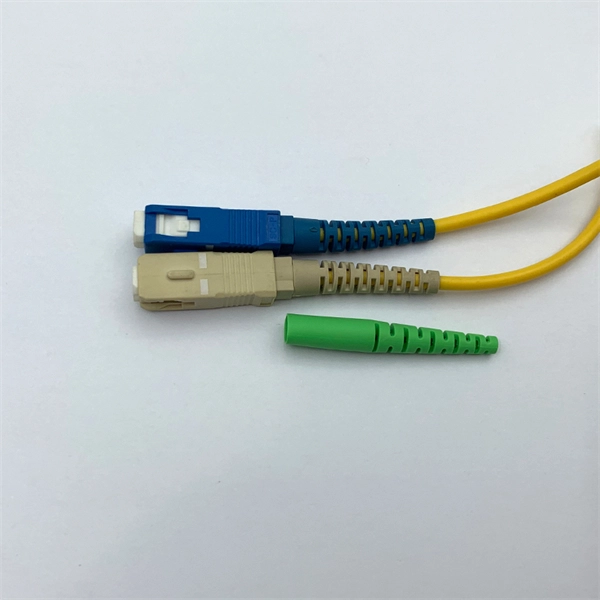
Every fiber optic patch cable has a rated attenuation and bandwidth. For example, OM1 is rated at 200 MHz·km at 850 nm and is intended for use in legacy applications. The higher OM ratings provide more speed and distance. Attenuation should remain within acceptable limits for reliable transmission. Executive Summary: Choosing the right fiber patch cable is one of the most consequential decisions in network infrastructure planning. The wrong choice — whether it's an underperforming multimode grade or an unnecessarily expensive singlemode run — can either cripple your network's reliability or. Fiber optic patch cords are key components for efficient, low-loss optical signal transmission between devices and fiber optic cabling links. One or both ends of the patch cord are equipped with standardized fiber optic connectors, and common interfaces include LC, SC, FC, ST, etc. They are manufactured and tested in compliance with TIA 604 (FOCIS), IEC 61754 and YD/T industry standards. OM1, OM2, OM3, OM4, OM5 or OS2 fiber types are available to meet the demand of. Fiber optic patch cables are ideal for supporting high speed telecommunication network fiber applications. They are lengths of optical fiber terminated with connectors on both ends. Their job is to connect two optical devices, like switches, routers, or optical transceivers that communicate.
[PDF]

MUSCAT: The Royal Oman Police (ROP) has reported a disruption to internet services in parts of South Al Sharqiyah Governorate after fibre optic cables belonging to a telecommunications provider were accidentally cut during construction work in the Wilayat of Sur. Royal Oman Police say repair work underway; services expected to be restored within hours. ROP said in a statement: "The Royal Oman Police announces a disruption in fiber optic connections belonging to a telecommunications. Microsoft said in a status update that the Middle East "may experience increased latency due to undersea fibre cuts in the Red Sea," but gave no other details. Fibre optic cables on the ocean Floor. File pic: iStock Internet access in parts of Asia and the Middle East was disrupted after undersea. „Oman Fiber Optic always offers great service with quality product. They have very good technical sales team and logistics team and are always available for support. „ „Professional supportive sales team with excellent material quality leading to a great service!„ Technology Integration on time. Sur – Royal Oman Police (ROP) has announced a significant disruption to their digital services within the South Sharqiyah Governorate following an accidental severance of fibre optic cables. The technical failure occurred in the Wilayat of Sur, where ongoing construction activities inadvertently.
[PDF]
In the single mode vs. multimode fiber debate, there is not one cable that's the best, but there are some that are better suited to certain situations. If you need to run fiber optic cable over a vast distance, there's.
[PDF]
In a fused fiber splitter, the input fiber is aligned with the fused region, which causes the optical power to be divided between the output fibers. The tapering process gradually guides the light from the input fiber to the output fibers, resulting in a proportional split of the. A fiber-optic splitter, also known as a beam splitter, is based on a quartz substrate of an integrated waveguide optical power distribution device, similar to a coaxial cable transmission system. The optical network system uses an optical signal coupled to the branch distribution. It plays a crucial role in enabling multiple devices to share a single fiber optic connection, maximizing the utilization of the available. Essentially, a fiber optic splitter performs the following actions: Light Enters: Light travelling through a fiber optic cable enters the splitter. Passive Separation: Inside the splitter, the light is split into multiple separate beams using optical components. Conversely, it can also combine multiple signals into one. Its primary role is in Passive Optical Networks (PON), which are the foundation of. A fiber optic splitter is a passive optical component that divides a single incoming optical signal into two or more outgoing signals, or combines multiple incoming signals into one. However, modern splitters can have multiple inputs and outputs, allowing for the distribution of a single signal to dozens of receivers. The internal workings of a passive.
[PDF]

Explore verified suppliers offering low-price fiber optic splice boxes, ideal for wholesale. With options from 24 to 144 cores, start your purchase from 1 unit at an average price around $17. TAKFLY COMMUNICATIONS CO. com! Source over 176 fiber-optic splice closures for sale from manufacturers with factory direct prices, high quality & fast shipping. We support our B2B partners with OEM branding, custom configurations, and bulk order discounts, delivering factory-tested solutions for large-scale. COYOTE Closure, 288f/576f ribbon max, Buffer Tube: 8. 5″ x 22″, Includes (1) 3 Section End Plate, (1) Blank End Plate, Organizer, and Lock Tape sealant. FOSC 600 D Dome Closure, 648ct Single/1728ct Ribbon, 8 Ports, Loaded Without Trays, 4 Ground Lugs, 32. 79″, Price Per Ea. ZIP code to view pricing. ZIP code to. Budco is a stocking distribution company for broadband tools, fiber optic tools and cable tools. Since 1970, Budco has provide cable construction tools, cable installation tools, and cable identification tools including fiber optic test equipment and tools for the telecommunications industry. We. This fiber optic splice box is an outdoor fiber optic splice closure used to protect the twisting and joining (splicing) of fiber optic cables. These splice boxes are not made for in-house, off-the-shelf cabling solutions. Instead, they are for installation by professionals laying new fiber optic.
[PDF]
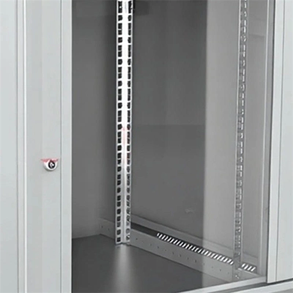
This splice case protect fiber optic cables and juction from outside plant environment damage. They are made of reinforced ABS or PC plastic, which has high strength and corrosion resistance. In addition, the splice enclosures are all hermetically sealing structure, waterproof and. Standard polycarbonate (PC) or Glassfibre reinforced (PC+GLAS) PP ABS (Acrylnitrile-butadiene -styrene) Slightly lower UV resistance compared with PC. Recommended for outdoor use if protected against weather influences GRP – GLASS FIBRE REINFORCED POLYESTER Polycarbonate and ABS enclosure materials. The fiber optic splice closure is a closed structure used for splicing, protecting and managing optical fibers. Its material selection is crucial to ensure the quality and service life of the fiber optic splice closure. These boxes are well suited as optical cable splice collection points for DAS (Distributed Antenna Systems), MTU (Multi-Tenant Unit) commercial business applications, and MDU (Multi-Dwelling Unit). It is a reentry box which is made of PC or PP material. The shells and the base are sealed with silicone gum. This product can be re-entered and used again after it is opened. Typically selected for high-density OSP splicing and branching. What is the basic structure of Fiber Optic Splice Closure? The basic structure of Fiber Optic Splice Closure includes the box body, box components, sealing ring, and lock buckle.
[PDF]

It is an interference type damper designed to attenuate the energy of cable vibration and restrain cable vibration amplitude by impacting with its damping section, so as to protect cables. Spiral vibration dampers have a helically-formed damping section sized for interplay of damper and cable to provide the action/reaction motion that opposed the natural vibration wave. The shock absorber damper is an interference type damper to attenuate vibration amplitude by impact with its damping section and especially designed for ADSS cable and OPGW cable of diameter less than. Spiral Vibration Dampers using its anti-vibration part to produce antihunt action to the wind vibration, consuming the vibration energy that produced by the cable running under the action of laminar wind,to prevent the destruction of gold tool and fiber optic cable, which mainly used for ADSS. Shop DigiKey's large in-stock selection of Spiral Wrap, Expandable Sleeving. View inventory, pricing and order now for same day shipping!.
[PDF]
Search below to explore initial fiber availability in your area. Login to your CarrierFinder account for detailed insights and full access to carrier data. Enter your address and discover fiber and broadband internet providers. We'll show you which fiber networks and providers serve your address and the best plans. Fiber broadband, or fiber internet, is powered by fiber optic cables and has the potential to transmit data at much higher speeds than DSL or cable internet. How do I know if I have AT&T home internet availability at my address? AT&T home internet availability depends on your address. This means. By integrating Frontier's complementary pure-play fiber network with Verizon's industry-leading Fios and mobility assets, the company now has an expanded reach of almost 30 million fiber passings across 31 states and Washington, D. With the greater availability of premium home internet and. Fiber internet is a broadband connection that runs on light signals from fiber-optic cabling, delivering multi-gig upload and download speeds. It's the fastest and most reliable internet you can get, and most plans come with straightforward pricing and included Wi-Fi equipment. The map will be updated continuously to improve its accuracy through a combination of FCC verification efforts, new data from Internet.
[PDF]

Home and business fiber optics projects typically range from a few hundred to several thousand dollars, depending on run length, fiber type, and labor needs. The main cost drivers are materials, installation time, and environmental factors that affect trenching, conduit, and terminations. Commercial building installations with 100-200 network drops generally range from $15,000 to $30,000. Single-mode fiber costs less per foot than multimode fiber, but it requires more. What is Fiber optic network design? Fiber optic network design involves the planning, routing, and drafting of Fiber cable layouts to support high-speed data transmission. It includes detailed mapping of backbone, distribution, and drop connections for FTTH, FTTP, FTTx, and enterprise networks. Fiber optic network design refers to the specialized processes leading to a successful installation and operation of a fiber optic network. It includes first determining the type of communication system (s) which will be carried over the network, the geographic layout (premises, campus, outside. According to ResearchAndMarkets, the global market for fiber optics was estimated at $5. 8 billion in 2022 and is expected to reach $11. This is the dominant broadband access technology across half of OECD countries today. The price landscape varies from basic drop cables to enterprise backbone runs, with per foot and per reel pricing common in estimates. This guide presents cost ranges.
[PDF]

Panjiva uses over 30 international data sources to help you find qualified vendors of Ecuadorian sensors. Get access to all 13 remaining Fiber optic products suppliers with complete contact information, addresses, and business details. As of May, 2026, we have compiled data. Pricing (USD) Filter the results in the table by unit price based on your quantity. Fiber Optic Sensors are available at Mouser Electronics. Mouser offers inventory, pricing, & datasheets for Fiber Optic Sensors. How does 6Wresearch market report help businesses in making strategic decisions? 6Wresearch actively monitors the Ecuador Distributed Fiber Optic Sensor Oil & Gas Market and publishes its comprehensive annual report, highlighting emerging trends, growth drivers, revenue analysis, and forecast. These results have not been confirmed by Panjiva and are provided on an "AS IS" basis, as further described in Panjiva's Terms and Conditions of Use and Panjiva's Transparency Policy. Your use of the information provided in these results is subject in all respects to those Terms and Conditions of. Furthermore, the expansion of smart cities and the adoption of the Internet of Things (IoT) are amplifying the demand for distributed fiber optic sensors. 7 million in 2024 and is projected to grow from USD 1,581.
[PDF]