When you see “PON” on your router, it stands for Passive Optical Network. This light indicates the status of your fiber connection to the network. Passive optical networking (PON), like active optical networking, uses fiber-optic cabling to provide Ethernet connectivity from a main data source to endpoints. While there are many subtle differences, a clear distinction between active optical networking and PON topology is PON's use of a. A passive optical network (PON) is a fiber-optic telecommunications network that uses only unpowered devices to carry signals, as opposed to electronic equipment. In practice, PONs are typically used for the last mile between Internet service providers (ISP) and their customers. The purpose of an OLT is to control, convert signals and coordinate fiber optic service (FiOS) within a PON system. An ONT. Turn off the router and disconnect the power cord. Locate the optical network (PON) port on your router. Inspect the PON cable for make sure that it is correctly connected to the router. Instead of running a separate fiber strand to every home or office, a PON shares a single fiber using optical.
[PDF]

This article provides a detailed technical comparison between fiber optic and copper cables, offering a clear perspective for engineers, network architects, and procurement managers. The core distinction between the two technologies lies in the physics of data. However, the exponential growth in data demand has positioned fiber optic technology as the superior alternative for performance, scalability, and future-readiness., 10G/25G/40G/100G and beyond depending on optics and reach). Copper Ethernet scales too, but practical limits are lower and depend. The two main options are fiber optic cables and copper cables, each with its own advantages and drawbacks. Fiber optic cables are praised for their high performance and scalability, while copper cables remain a cost-effective choice, especially for budget-conscious projects and older systems. Copper wire is more susceptible to interference and has limited data capacity, making optical fiber the preferred choice for modern high-speed. Optical connectivity, utilizing fiber-optic technology, has emerged as the superior choice for modern networking, offering unparalleled performance, reliability, and scalability. For example, a typical 10 Gbps copper Ethernet link (such as Cat 6A) over 100 meters can consume approximately 5 to 8+.
[PDF]
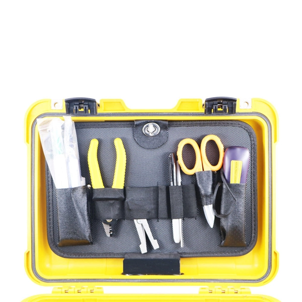
This precision cleaner quickly cleans the end faces of fiber optic connectors, while eliminating electrostatic charge, which can attract airborne contaminants to the end face. Talk to a knowledgeable OCC Expert that can find or customize a product to fit your specifications. . Chemtronics is the industry leader for fiber optic cleaning products, providing performance, convenience, time savings and cost savings. Cleaning fiber optic connectors is fast, easy and reliable with our highly engineered solvents, lint-free swabs, precision wipes, and cleaning platforms. AFL offers a complete selection of compact fiber optic cleaning kits for field cleaning of connector end-faces and splicer v-grooves. Fluke Networks Fiber Optic Cleaning Kits contain the best fiber optic cleaning tools and products to effectively remove the toughest contaminants in any optical fiber cable (OFC) network. 800-622-7711. Specialized Products provides a variety of optical fiber, end face and splice prep kits from leading fiber optics brands including Sticklers, Chemtronics, AFL and Fluke Networks. These kits are designed to include everything the fiber technician may need while working in the field.
[PDF]
A fiber optic switch allows optical signals to be selectively switched from one fiber to another, while a fiber optic splitter divides an optical signal into multiple signals, allowing it to be transmitted to multiple devices. It is essentially a switch that operates at the optical layer of a network, rather than at the electrical layer. Conversely, it can also combine multiple signals into one. Its primary role is in Passive Optical Networks (PON), which are the foundation of. A fiber optic splitter is a passive optical component that divides a single incoming optical signal into two or more outgoing signals, or combines multiple incoming signals into one. The optical network system uses an optical signal coupled to the branch distribution. The fiber optic. While the splitter doesn't manage or direct traffic like a switch, it does allow multiple devices to access the same network connection. The devices connected to the splitter typically need to be configured to work with the shared connection, and bandwidth may be divided among the devices based on. A passive device used to split or combine signals on fiber optics may be called a splitter, combiner or coupler, but splitter is the most common term. They have been used since the 1980s to create networks and provide the technology for today's passive optical networks used in fiber to the home.
[PDF]

In addition, fiber optic splitter can also be employed in the maintenance of long-haul network, cable TV ATM circuit or local area/metro area network. Technology drives the broader adoption of passive optical LAN (also known as a passive optical local area network) across various sectors. Not having a long history as a passive optical network (PON), it is a better replacement for copper-based LANs in local area networks. This article covers every. Optical LAN is optimized for modern fiber-based network connectivity inside buildings and across campus. Learn more in this blog. For decades, businesses have successfully deployed traditional local area networks (LANs) to transmit their critical data—and many continue to rely. These unassuming devices enable a single optical signal to be divided into multiple paths, making them indispensable for sharing network resources efficiently—from residential FTTH (Fiber-to-the-Home) connections to large-scale telecom backbones. A PON delivers data from the center office of an ISP to multiple Optical Network Terminals (ONTs) on users' ends. Similar to PON system, passive optical LAN employs single-mode fiber cabling and uses. What is a Fiber Optic Local Area Network (Fiber Optic LAN)? A local area network, or LAN, is a geographically limited network intended for the local transport of voice, data, and video. It can be a small.
[PDF]

MUSCAT: The Royal Oman Police (ROP) has reported a disruption to internet services in parts of South Al Sharqiyah Governorate after fibre optic cables belonging to a telecommunications provider were accidentally cut during construction work in the Wilayat of Sur. Royal Oman Police say repair work underway; services expected to be restored within hours. ROP said in a statement: "The Royal Oman Police announces a disruption in fiber optic connections belonging to a telecommunications. Microsoft said in a status update that the Middle East "may experience increased latency due to undersea fibre cuts in the Red Sea," but gave no other details. Fibre optic cables on the ocean Floor. File pic: iStock Internet access in parts of Asia and the Middle East was disrupted after undersea. „Oman Fiber Optic always offers great service with quality product. They have very good technical sales team and logistics team and are always available for support. „ „Professional supportive sales team with excellent material quality leading to a great service!„ Technology Integration on time. Sur – Royal Oman Police (ROP) has announced a significant disruption to their digital services within the South Sharqiyah Governorate following an accidental severance of fibre optic cables. The technical failure occurred in the Wilayat of Sur, where ongoing construction activities inadvertently.
[PDF]

Explore verified suppliers offering low-price fiber optic splice boxes, ideal for wholesale. With options from 24 to 144 cores, start your purchase from 1 unit at an average price around $17. TAKFLY COMMUNICATIONS CO. com! Source over 176 fiber-optic splice closures for sale from manufacturers with factory direct prices, high quality & fast shipping. We support our B2B partners with OEM branding, custom configurations, and bulk order discounts, delivering factory-tested solutions for large-scale. COYOTE Closure, 288f/576f ribbon max, Buffer Tube: 8. 5″ x 22″, Includes (1) 3 Section End Plate, (1) Blank End Plate, Organizer, and Lock Tape sealant. FOSC 600 D Dome Closure, 648ct Single/1728ct Ribbon, 8 Ports, Loaded Without Trays, 4 Ground Lugs, 32. 79″, Price Per Ea. ZIP code to view pricing. ZIP code to. Budco is a stocking distribution company for broadband tools, fiber optic tools and cable tools. Since 1970, Budco has provide cable construction tools, cable installation tools, and cable identification tools including fiber optic test equipment and tools for the telecommunications industry. We. This fiber optic splice box is an outdoor fiber optic splice closure used to protect the twisting and joining (splicing) of fiber optic cables. These splice boxes are not made for in-house, off-the-shelf cabling solutions. Instead, they are for installation by professionals laying new fiber optic.
[PDF]
Search below to explore initial fiber availability in your area. Login to your CarrierFinder account for detailed insights and full access to carrier data. Enter your address and discover fiber and broadband internet providers. We'll show you which fiber networks and providers serve your address and the best plans. Fiber broadband, or fiber internet, is powered by fiber optic cables and has the potential to transmit data at much higher speeds than DSL or cable internet. How do I know if I have AT&T home internet availability at my address? AT&T home internet availability depends on your address. This means. By integrating Frontier's complementary pure-play fiber network with Verizon's industry-leading Fios and mobility assets, the company now has an expanded reach of almost 30 million fiber passings across 31 states and Washington, D. With the greater availability of premium home internet and. Fiber internet is a broadband connection that runs on light signals from fiber-optic cabling, delivering multi-gig upload and download speeds. It's the fastest and most reliable internet you can get, and most plans come with straightforward pricing and included Wi-Fi equipment. The map will be updated continuously to improve its accuracy through a combination of FCC verification efforts, new data from Internet.
[PDF]
This splice case protect fiber optic cables and juction from outside plant environment damage. They are made of reinforced ABS or PC plastic, which has high strength and corrosion resistance. In addition, the splice enclosures are all hermetically sealing structure, waterproof and. Standard polycarbonate (PC) or Glassfibre reinforced (PC+GLAS) PP ABS (Acrylnitrile-butadiene -styrene) Slightly lower UV resistance compared with PC. Recommended for outdoor use if protected against weather influences GRP – GLASS FIBRE REINFORCED POLYESTER Polycarbonate and ABS enclosure materials. The fiber optic splice closure is a closed structure used for splicing, protecting and managing optical fibers. Its material selection is crucial to ensure the quality and service life of the fiber optic splice closure. These boxes are well suited as optical cable splice collection points for DAS (Distributed Antenna Systems), MTU (Multi-Tenant Unit) commercial business applications, and MDU (Multi-Dwelling Unit). It is a reentry box which is made of PC or PP material. The shells and the base are sealed with silicone gum. This product can be re-entered and used again after it is opened. Typically selected for high-density OSP splicing and branching. What is the basic structure of Fiber Optic Splice Closure? The basic structure of Fiber Optic Splice Closure includes the box body, box components, sealing ring, and lock buckle.
[PDF]

Every fiber optic patch cable has a rated attenuation and bandwidth. For example, OM1 is rated at 200 MHz·km at 850 nm and is intended for use in legacy applications. The higher OM ratings provide more speed and distance. Attenuation should remain within acceptable limits for reliable transmission. Executive Summary: Choosing the right fiber patch cable is one of the most consequential decisions in network infrastructure planning. The wrong choice — whether it's an underperforming multimode grade or an unnecessarily expensive singlemode run — can either cripple your network's reliability or. Fiber optic patch cords are key components for efficient, low-loss optical signal transmission between devices and fiber optic cabling links. One or both ends of the patch cord are equipped with standardized fiber optic connectors, and common interfaces include LC, SC, FC, ST, etc. They are manufactured and tested in compliance with TIA 604 (FOCIS), IEC 61754 and YD/T industry standards. OM1, OM2, OM3, OM4, OM5 or OS2 fiber types are available to meet the demand of. Fiber optic patch cables are ideal for supporting high speed telecommunication network fiber applications. They are lengths of optical fiber terminated with connectors on both ends. Their job is to connect two optical devices, like switches, routers, or optical transceivers that communicate.
[PDF]
In the single mode vs. multimode fiber debate, there is not one cable that's the best, but there are some that are better suited to certain situations. If you need to run fiber optic cable over a vast distance, there's.
[PDF]

Home and business fiber optics projects typically range from a few hundred to several thousand dollars, depending on run length, fiber type, and labor needs. The main cost drivers are materials, installation time, and environmental factors that affect trenching, conduit, and terminations. Commercial building installations with 100-200 network drops generally range from $15,000 to $30,000. Single-mode fiber costs less per foot than multimode fiber, but it requires more. What is Fiber optic network design? Fiber optic network design involves the planning, routing, and drafting of Fiber cable layouts to support high-speed data transmission. It includes detailed mapping of backbone, distribution, and drop connections for FTTH, FTTP, FTTx, and enterprise networks. Fiber optic network design refers to the specialized processes leading to a successful installation and operation of a fiber optic network. It includes first determining the type of communication system (s) which will be carried over the network, the geographic layout (premises, campus, outside. According to ResearchAndMarkets, the global market for fiber optics was estimated at $5. 8 billion in 2022 and is expected to reach $11. This is the dominant broadband access technology across half of OECD countries today. The price landscape varies from basic drop cables to enterprise backbone runs, with per foot and per reel pricing common in estimates. This guide presents cost ranges.
[PDF]

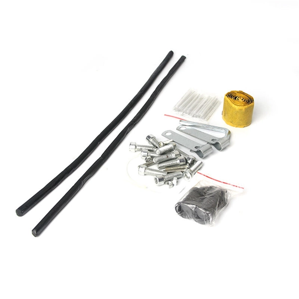
It is an interference type damper designed to attenuate the energy of cable vibration and restrain cable vibration amplitude by impacting with its damping section, so as to protect cables. Spiral vibration dampers have a helically-formed damping section sized for interplay of damper and cable to provide the action/reaction motion that opposed the natural vibration wave. The shock absorber damper is an interference type damper to attenuate vibration amplitude by impact with its damping section and especially designed for ADSS cable and OPGW cable of diameter less than. Spiral Vibration Dampers using its anti-vibration part to produce antihunt action to the wind vibration, consuming the vibration energy that produced by the cable running under the action of laminar wind,to prevent the destruction of gold tool and fiber optic cable, which mainly used for ADSS. Shop DigiKey's large in-stock selection of Spiral Wrap, Expandable Sleeving. View inventory, pricing and order now for same day shipping!.
[PDF]