The communication system of fiber optics is well understood by studying the parts and sections of it. The major elements of an optical fiber communication system are shown in the following figure. The ba.
[PDF]
Among the most important emerging trends in fiber optic technology for 2025 are: Ultra-low loss (ULL) fiber, extending long-distance data transmission with minimal signal degradation. Bend-insensitive fiber, delivering reliable performance in tight urban and data center installations. With speeds reaching 100Gbps, 400Gbps, 800Gbps, and. According to a recent study by the Fiber Broadband Association and RVA, 76. 5%) are now serviceable by fiber—an increase of 13% in 2024. By 2028, fiber is expected to reach 80% of U. As the industry looks ahead, six major trends are shaping the future of fiber. The global FTTH market size is estimated at $47 billion in 2022 and is projected toward upward growth at a compound annual growth rate (CAGR) of 12% from 2023 to 2030. Born of a wildly successful experiment The evolution of FTTH networks dates to the 1970s, to an experiment with fused silica. The. From multi-gigabit speeds to open-access models and AI-driven optimization, what's on the horizon suggests that the fiber broadband industry is not just growing – it's transforming. Continued Expansion in Global Coverage The. The future of Fiber Optic communication is on the brink of remarkable advancements, setting the stage for groundbreaking innovations that will shape our daily lives. From enabling high-speed internet connections to.
[PDF]

These core components of optical fiber communication system — transmitter, optical fiber, receiver, plus supporting elements like amplifiers and multiplexers — enable lightning-fast, interference-free communication over vast distances. Fiber optic communication refers to a method of transmitting data that utilizes light instead of electrical signals to send information through optical fibers. It works on the principle of total internal reflection, allowing light to move through the fiber with very little loss. The process kicks. In order to comprehend how fiber optic applications work, it is important to understand the components of a fiber optic link. Simplistically, there are four main components in a fiber optic link (Figure 1). These systems rely on three vital components working together – the communication channel, the optical transmitter, and the optical receiver. Optical fiber communication system 1. Encoder Encoder converts the analog information like voice, figures, objects etc into the binary data. Optical fibers are thin, flexible strands of glass or plastic that serve as the medium for transmitting light signals. Some exceptional characteristic features of this type of communication system like large bandwidth, smaller diameter, lightweight, long-distance signal.
[PDF]

In telecommunications, a base station is a fixed transceiver that is the main communication point for one or more wireless mobile client devices. It further connects the device to other. A communication base station is composed of a computer room, base station, antenna, feeder line (transmission line between transmitter and antenna), and supporting equipment. The antenna is at the top of the signal tower, and below the tower is a computer room. Along with increased capacity demands driven by the explosion of cloud and connected device growth, engineers need interconnects that enhance the design. A base transceiver station (BTS) or a baseband unit (BBU) is a piece of equipment that facilitates wireless communication between user equipment (UE) and a network. UEs are devices like mobile phones (handsets), WLL phones, computers with wireless Internet connectivity, or antennas mounted on. Fiber Optic Cables: High-speed fiber optic cables connect the BBU to the RRUs (RE part). Signal Transmission: The optical signals carry data, control, management, and synchronization information. Topology: The BBU and multiple radio heads can be connected in cascade or star configurations. The rise. The design investigates the possibilities of Free-Space Optical (FSO) communication systems and MilliMeter-Wave (MMW) technologies operating at 60. Although these technologies are highly effective and have a high throughput, they are nevertheless vulnerable to weather phenomena like rain.
[PDF]

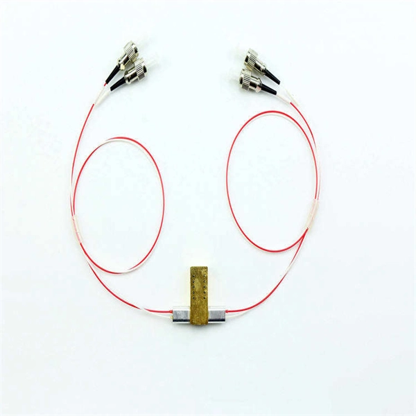
Optical couplers can split or join signals in fibers. You can connect many users to one port with 1:n or 2:n splitters. These devices work both ways, which helps strong network communication. They help send. This small device connects or joins optical fibers together. It helps networks grow and change when needed. Learn about the two main types of fiber optic couplers: fused and planar. Fused. How to Choose the Right Fiber Coupler (FTTH, Data Center & More) Are you in the process of designing a Fiber to the Home (FTTH) network, but wondering how to split one fiber for multiple users? Or maybe you are operating a data center, and you would like to use a single signal to provide to. Fiber optic couplers are optical devices that connect three or more fiber ends, dividing one input between two or more outputs, or combining two or more inputs into one output. The device allows the transmission of light waves through multiple paths. Fiber optic couplers can either be passive or. A fiber optic coupler is a passive optical component that splits, combines, taps, or redistributes light between optical fibers. In real-world networks, couplers let one signal reach many users, allow several signals to share one fiber path, or sample a small amount of light for monitoring. 5/125 µm fiber, with low insertion loss and a broad operating wavelength range from 800 to 1600 nm. The 1x2 and 2x2.
[PDF]

When it comes to testing fiber optic cables, a Visual Fault Locator (VFL) is an essential tool in your toolkit. A VFL is used to detect faults, breaks, or bends in fiber optic cables by emitting a bright red light that is visible even through the fiber's jacket. Let's dive into everything you need to know about mastering VFLs. In the. Finding a break in a fiber optic cable can be challenging but is essential for maintaining a stable network. Common Indicators of a Cable Break Signal. Here Kingfisher's experienced engineers share their experience in best practices and procedures for fiber optic testing related mostly to installation and maintenance. We hope that by sharing our knowledge, we will help grow our industry. Please enjoy & pass on these notes. The following are key methods and techniques used for optical fiber cable line failure positioning: Visual Inspection: Perform a visual inspection of the. Locating faults in fiber optic cables requires specialized tools and techniques. Look for dirt, scratches, or damage on the connectors. Clean. To ensure the quality and continuity of fiber optic services, it is essential to identify and locate fiber optic cable faults as quickly and accurately as possible. In this article, you will learn about some of the common methods and tools for fiber optic testing and troubleshooting.
[PDF]

Also, please take a look at the list of 44 communication cable manufacturers and their company rankings. Quabbin Wire & Cable Co. *Including some distributors, etc. On the Thomas Network, you'll find more than 3200 suppliers of cables in the US. You can filter these companies by location, certifications, and more factors to easily find and connect with the right supplier for your needs. We've listed the most frequently sourced cable suppliers below: Philatron. This section provides an overview for communication cables as well as their applications and principles. Dacon Systems. From Fiber Optic to Copper Cables, from the most innovative products to the smartest solutions, from industries such as Broadcast or Enterprise to Industrial or Data Center, OCC has the connections you need. We have the resources, innovative technology and industry expertise to meet the growing needs of customers around the corner and around the world. Whatever the application, our in-house engineering team of compound, process and. NAI is a global leader in the manufacturing of advanced high-reliability connectivity solutions for mission critical and other high-performance applications. Our world class integrated supply chain and operations management, combined with a global footprint in lower cost regions, provide our. Browse our broad range of connectivity products designed to help enable your communication networks. Easily create a bill of materials list.
[PDF]

In this guide, you will find a chronological description of the fusion splicing process, the principal technical standards, and answers to the real-life questions network engineers and procurement teams may have. TMM P021 OPTIC FIBRE CABLE JOINING, TERMINATION & MANAGEMENT Version 9. Therefore, we will also touch on cost factors, risk management, and best practices in. Fusion Splicing • Splicing is the process of connecting two bare fibres directly without any connectors. • Splicing provide much lower insertion loss compared to fiber connectors that's why Splicing is preferred over the use of Connectors. Fiber mechanical splicing – Insertion loss < 0. 5dB Fiber. What is Fiber Optic Splicing and Why is it Needed? – #1. Ensure Your Splicing Tools are Clean – #2. 56 was approved by ITU-T Study Group 6 (2001-2004) under the ITU-T Recommendation A. 8 procedure on 14 May 2003. The International Telecommunication Union (ITU) is the United Nations specialized agency in the field of telecommunications. By following the step-by-step guide provided, you can effectively perform fusion splicing to maintain high-quality fiber optic.
[PDF]

This Code consists of the introduction, definitions, grounding rules, lists of referenced and bibliographic documents, and Parts 1, 2, 3, and 4 of the 2023 Edition of the National Electrical Safety Code. The Institute of Electrical and Electronics Engineers, Inc. 3 Park Avenue, New York, NY. Climbing Space is an unobstructed, vertical space along the side or corner of the pole. In gen-eral, it consists of an imaginary box, 30-inches square, extending at least 40 inches above the highest communications cable or other facility and 40 inches below the lowest communications cable or other. The Fiber Optic Association, Inc. (FOA) was founded in 1995 to help develop the workforce to build the fiber optic networks to support a rapid expansion in communications and the Internet. The charter of the FOA was to promote professionalism in fiber optics through education, certification, and. There are a number of ways of finding out more about cabling standards. You can buy a complete copy of the EIA/TIA or ISO/IEC standards which can be very expensive and wade through page after page of standards language. You can also get catalogs and/or visit the websites of a number of cabling. to n utral comm.
[PDF]

Search by part number or description such as CAT5, CAT6, OSP, etc. Sort by any of the table headers. Use the drop down menu to filter by product category and type. Sort by any. Welcome to the Corning LANscape® Solutions Product Drawings Resource Center, your complete source for our optical hardware component drawings. The two-dimensional and isometric hardware products drawings are available in PDF (Adobe® Acrobat®), DXF (AutoCAD®), VSS (Visio® Stencil) formats, and. Free CAD and BIM blocks library - content for AutoCAD, AutoCAD LT, Revit, Inventor, Fusion 360 and other 2D and 3D CAD applications by Autodesk. CAD blocks and files can be downloaded in the formats DWG, RFA, IPT, F3D. You can exchange useful blocks and symbols with other CAD and BIM users. When possible we have included both linear and nonlinear cable models for your use as appropriate. The use of a linear cable model may be acceptable for calculating loads and sags in an as-built situation such as joint use applications, or when linear elastic behavior and nominal creep are desired. The two linetypes are shown below. The appearance is similar but slightly different. Does anyone have such a code that they could share with me? I struggled for an hour or so and came up with this. There is a small gap on the left side of the circle.
[PDF]
The Open Systems Interconnection (OSI) model is a developed by the (ISO) that "provides a common basis for the coordination of standards development for the purpose of systems interconnection." In the OSI reference model, the components of a communication system are disting.
[PDF]

l LongXing GPJ83-D18 fiber optic splice closures are specially designed to protect joints of optic cable. l The scope of application is: aerial, wall-mounting, and pole-mounting. The ambient temperature ranges from –40℃ to +65℃. l The closure adopts mechanical and heat shrinkable. The GPJ83-D18 Dome Fiber Optic Splice Closure are closures which accommodate the joint part of the cable, that can be used in aerial-hanger, wall-mounting or pole-mounting. This kind of dome splice closure includes three types, namely GPJ83-D18-A, GPJ83-D18-B, GPJ83-D18-C, GPJ83-D18-D, which. –High strength dust proof and waterproof function, suitable for aerial installation –The box body adopt push pull mechanical locking mode, with design of buckle type, easy to operate, reusable and reliable –Adapter and splitter can be assembled, 18pcs adapter can be equipped UV, 2pcs micro. Up-down bisection GPJ-M is an arc, horizontal type. Innovative insert plates and fixing bolts are used to fix and seal FOSC, and its installation is quite simple. The FOSC is suitable for protecting fiber cable splices in straight-through and branching applications. Speed Optic' s closures can be divided into two series: horizontal type and dome type. As for dome type, according to the sealing ways, including shrinkable. Dome GPJ-O is a vertical type. GPJ-O is provided with 4 fiber cable inlet/outlet ports and sealing is achieved by tightening nut after inserting fiber cable.
[PDF]

Learn how to splice fiber optic cable using fusion splicing with this complete step-by-step guide. Includes tools, best practices, loss standards (ITU-T G. 652), cost analysis, and FAQs for network engineers and installers. Splicing fiber optic cable is an extremely important phase for making dependable, high-speed communication infrastructures. Regardless of the type of fiber network you're deploying, be it for telecom, enterprise data centers, or smart city infrastructure, fusion splicing provides the benefits of. This is where fiber optic cable splicing—the process of creating a permanent, high-performance join between two fiber ends—becomes critical. For network managers and technicians, a poor splice can lead to significant signal degradation, network downtime, and costly troubleshooting. At Turn-Key. Think of a fiber optic cable splice as the seamless stitching that keeps data flowing through the delicate threads of a network—like a master tailor joining fabric with precision. What is Fiber Optic Splicing and Why is it Needed? – #1. Discover how to efficiently use sleeves and the heat. The answer lies in splicing, both fusion and mechanical. In this comprehensive guide, we will delve into when.
[PDF]

