
Scattering accounts for the greatest amount of attenuation in a fiber cable, between 95 and 97 percent. Light traveling through the fiber interacts with the densities as shown in the light and is then partially scattered in all directions. Fiber optic cables have many advantages, but one of the downsides just like with copper cable, is that it can experience what is called attenuation. Attenuation refers to the loss of light as it travels down the fiber. This can be due to a variety of factors: scattering and absorption, intrinsic. This attenuation is inevitable, so the smaller the attenuation value, the longer the transmission distance of the same optical power. The better the quality of this fiber patch cable. It indicates the amount of signal reflected back. At TREND Networks, we are frequently asked how much loss is allowed when conducting testing on fiber optic cabling. Unfortunately, it is not a simple answer and depends on several factors. So how do you determine acceptable loss? When testing fiber optic cabling, determining acceptable loss is. Understanding fiber loss is vital in maintaining a reliable, efficient network. Understanding it is crucial for anyone involved in data centers, telecommunications, or enterprise networking. Here are the details and instructions about each field and how they contribute to the calculation: 1. Attenuation Coefficient (dB/km): This value represents the inherent signal loss per kilometer of.
[PDF]

An MPO fiber optic patch cord is a multi-core fiber pre-terminated patch cord that uses an MPO connector, mainly used for rapid connections between devices in high-density fiber optic cabling systems. Fiber cores are the heart of fiber optic cables, transmitting light signals that carry data. Made from either high-quality glass or plastic, the core plays a critical role in determining the cable's performance. The total number of cores for a 1pc fiber patch cable is calculated as the number of. Connecting fiber optic cables to patch panels may seem like a straightforward task, but improper connections can lead to signal loss, decreased network efficiency, and even costly repairs. That's why understanding the proper techniques and tools for this process is essential. In this post, you'll. The number of optical cores in an optical fiber is the total number of equipment interfaces multiplied by 2, plus 10% to 20% of the spare quantity, and if the communication mode of the equipment has serial communication and equipment multiplexing, you can reduce the number of cores. They realize high-density, high-efficiency fiber optic interconnection solutions through multi-core fiber connection technology. This article will comprehensively.
[PDF]

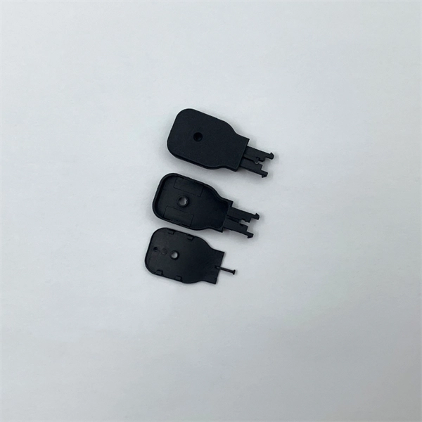
Mainly 9steps: Step 1: cut cable with cutting machines in lengths Step 2: put the connector spare parts on the cable Step 3: Strip cable jacket, coating till bare fiber, and make all parts in ready Step 4: Insert fiber into ferrule, glue dispenser and heat oven Step 5:. Mainly 9steps: Step 1: cut cable with cutting machines in lengths Step 2: put the connector spare parts on the cable Step 3: Strip cable jacket, coating till bare fiber, and make all parts in ready Step 4: Insert fiber into ferrule, glue dispenser and heat oven Step 5:. Learn how to make a fiber optic patch cord step by step, from preparation to testing, for reliable high-performance connections. Most guides on making fiber optic patch cord 1 s feel incomplete. They often focus on the final assembly steps, leaving the foundational stages a mystery. From cable cutting to connector assembly and testing, you will gain valuable insights into the production of. Fiber optic patch cords and Pigtails are very important passive fiber optic components in fiber optic networks. Use the fiber optic cleaver to cut the. This document describes the installation and use of the mode-conditioning patch cords listed in Table 1. A mode-conditioning patch cord is shown in Figure 1 IEEE 802. 3z-compliant optical fiber assembly consisting of a single-mode fiber permanently coupled off-center to a 62. 5-micron multimode.
[PDF]

Typical total project ranges and per-meter ranges with assumptions: A straightforward indoor fiber install with standard single-mode cable might cost about $0. 50 per meter for cable alone, with total project costs commonly in the $0. 50 per meter range when including. The cost per foot of fiber optic cable is now the lowest it's been since 2021. Labor dominates the installed price. 80 per ft – fastest, lowest cost. Directional boring (road. Buying fiber optic installation services involves several cost components, with total price influenced by length, location, and access. The main cost drivers include trenching or aerial deployment, materials, labor hours, and any required permits. How do you navigate these costs effectively? The pricing of single-mode fiber optic cables varies significantly based on. The initial cost of installing fiber optic cables can vary depending on the chosen installation method and specific project requirements. Total Project Costs: For commercial installations, expect costs ranging from $5,000 to $20,000 per mile for underground projects and from $40,000 to $60,000 per. Check each product page for other buying options. Need help?. In this article, we'll take a closer look at the main parameters determining the price of a fiber patch cord, provide up-to-date pricing ranges, and assist you in becoming a smarter buyer—regardless of whether you are making a purchasing decision for a project, replenishing inventory, or placing an.
[PDF]

Based on export compliance, verified UL E-files, and consistency in quality control, here are the top 5 Chinese manufacturers producing UL-rated fiber patch cords suitable for enterprise safety in 2025. Before we get to the manufacturers, let's be real about why we are. T&S Communications specializes in a wide range of fiber optic connectivity products, including standard fiber optic patch cords. They offer various types of patch cords, such as simplex, duplex, single-mode, and multi-mode, with different connector options, ensuring high-quality performance for. Fiber optic patch cords are short-distance fiber optic cables used to connect fiber optic equipment. It realizes high-speed and stable data transmission and communication through optical signal transmission. Patch cord has a various application including data centers, network equipment connections. Zhejiang specializes in fiber patch cords and accessories, benefiting from port access for exports. Industrial parks like Wuhan's "Optics Valley" foster R&D partnerships between manufacturers and universities. A “certification” on a. China is home to some of the world's leading fiber optic cable manufacturers, playing a crucial role in global fiber optic communication. As factory-terminated and precisely polished assemblies, they ensure low insertion loss and easy installation. Available in both Singlemode and Multimode configurations, our.
[PDF]

Instructional video on how to assemble your full-beam log splitter of 25-37 tons. championpowerequipment. comParts Store: https://shop. This manual contains important safety precautions which should be read and understood before operating the product. Failure to do so could result in serious injury. Specifications, descriptions and illustrations in this manual are as accurate as known at. se of a Champion Power Equipment (CPE) product. CPE designs, builds, and supports all of our p oducts to strict specifications and guidelines. With proper product knowledge, safe use, and regular maintenance, this p gers and maintenance of the product before use. Fully familiarize yourself, and. DO NOT operate the log splitter inside any building, including garages, basements, crawlspaces, sheds, or enclosure. DO NOT allow exhaust fumes to enter a confined area through windows, doors, vents or other openings. Using an engine indoors CAN KILL YOU IN MINUTES. Quick-disconnect cordsets allow sensor, lighting and safety devices to be replaced or moved quickly and are available in both single- and double-ended models. For added versatility or challenging applications, splitters, cables, and field wireable connectors are available to complete your system.
[PDF]

A bridge funnel is a marketing strategy that involves creating a simple, two-page funnel to bridge the gap between a free and paid offer. The first page of the funnel should include a headline, a brief description of the free offer, and a CTA to capture the visitor's email address. This powerful marketing strategy, known as bridge page funnels, enhances the effectiveness of affiliate product sales by acting as a SMOOTH TRANSITION between your traffic source and your main offer. It's like building a GOLDEN BRIDGE that guides potential customers straight to your doorstep. It "bridges" the gap between cold prospects and a purchase decision. The typical bridge funnel structure. A bridge funnel is a special funnel strategy that can turn less potential traffic into interested buyers before driving them to the affiliate product. The trick is to use a bridge page to hook the prospect before referring him/her to the product. Why do you. We will show you how to build a bridge funnel, and how to use the bridge funnel in business. Funnel marketing has become quite popular nowadays. This is because everything is now based online. Those who previously purchased from the offline business are now selling everything online.
[PDF]

In this video, I'll show you how to build a simple and effective short circuit protection circuit using a relay. This DIY project is perfect for anyone looking to protect their electronics from accidental shorts. Last Updated on February 15, 2026 by Swagatam 117 Comments In this post I will try to explain the making of a simple 220 V, 120 V AC mains short circuit breaker using an SCR and a triac combination, (researched and designed by me). The circuit is an electronic version of the normal main circuit. One possible solution to the problem of overcurrent is to use a variable bench power supply with a current limit function. These power supplies allow You to set a current limit, preventing a high current flow when a mistake occurs. This circuit will. Why Publish? How to Make Short Circuit Protection Circuit: Hii friend, Today I am going to make a circuit for Short Circuit protection. This circuit we will make using 12V Relay. How this circuit will Work - when short circuit will occur on the load side then the circuit will be automatically cut o. In this tutorial, we will see how to make a short circuit protection using Relay. Many times accidentally terminals of batteries and other power supplies get short-circuited. Due to this, they get hot and start degrading. In the case of lithium-ion or lithium-polymer batteries, they may catch fire.
[PDF]

Our guide delivers actionable, step-by-step best practices for rack layout, cable management, and patch panel installation. Following these steps helps you build a clean and efficient structured cabling system that simplifies maintenance and maximizes network performance. Patch panels are one of the best ways to manage an expansive local area network (LAN) by providing quick and easy access to the ports and connections that connect them altogether. Before a single cable is. H. Use cabinet screws to fix the network patch panel to the network cabinet. Note the wiring sequence on the patch panel when wiring, as T568A and T568B have different sequences. Different brands of patch panels may also have different wiring sequences, so always pay attention to the sequence. A patch panel is a board that houses multiple network ports. It acts as a bridge between incoming and outgoing Ethernet cables. Instead of plugging and unplugging devices directly from network switches, you connect them to the patch. Patch panels are a crucial component in any network infrastructure, providing a centralized location for managing cables and connections. By using patch panels, network administrators can simplify cable management, improve network scalability, and reduce downtime. This innovative tool combines precision with automation, ensuring accurate network documentation for IT professionals and network administrators.
[PDF]
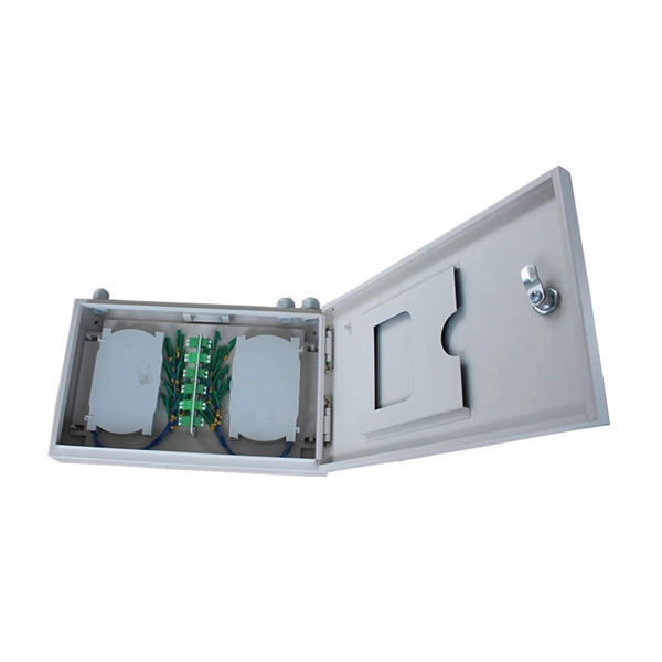
Here's a step-by-step guide to help you properly arrange fiber optic patch panels in a data center environment. Before installation, assess your network's current and future needs:. Effectively arranging optical fiber optic patch cords in a cabinet is a critical aspect of maintaining a streamlined and organized network infrastructure. Proper arrangement not only enhances the overall aesthetics of the cabinet but also plays a crucial role in preventing signal interference and. As networks move to higher speeds and higher density, choosing the right fiber optic patch cords becomes critical to the reliability of your system. At ZION Communication, we design and manufacture a full range of fiber patch cords for: This guide will help you quickly understand the main types of. You need fiber patch cord installation and maintenance for a strong network. If you do not handle them well, connectors can get misaligned. Rough handling can also cause problems. Fiber optic patch cords, also known as fiber optic patch cables or fiber jumpers, are indispensable components in modern optical networks. They act as the critical link for interconnecting devices like optical switches, servers, and distribution frames. Understanding the various technical. You need fiber optic cables. But the options are overwhelming. One customer ordered 50 LC-SC patch cords. They were all the wrong polish type. The network failed during testing. This happens more than you think.
[PDF]

Long Expansion Cycle: Optical fiber preform production has high technological barriers, and the expansion cycle can take as long as 18-24 months. Even if manufacturers start expanding immediately, the new capacity will not be available until at least 2027. This phenomenon is the result of multiple factors, including tight supply of optical fiber preforms (preforms), long expansion cycles for optical fiber production capacity, and the explosive growth of emerging applications such as AI computing power and drones. The expansion cycle of optical fibers is generally less than 6 months, and fiber optic cables can take 3 months. The expansion of production requires the purchase of equipment and the construction of factories. At the heart of this transformation lies fiber optic cable manufacturing, a precise and sophisticated process that powers our interconnected world. With the global fiber optic market reaching $6 billion and growing at 10% annually, the need for high-quality manufacturing solutions has never been. The manufacturing process of fiber optic cables involves several intricate steps that culminate in the production of high-performance data transmission solutions. This process begins with the creation of a preform, which serves as the foundation for the optical fibers within the cable. This intricate process combines cutting-edge technology, precise engineering, and.
[PDF]
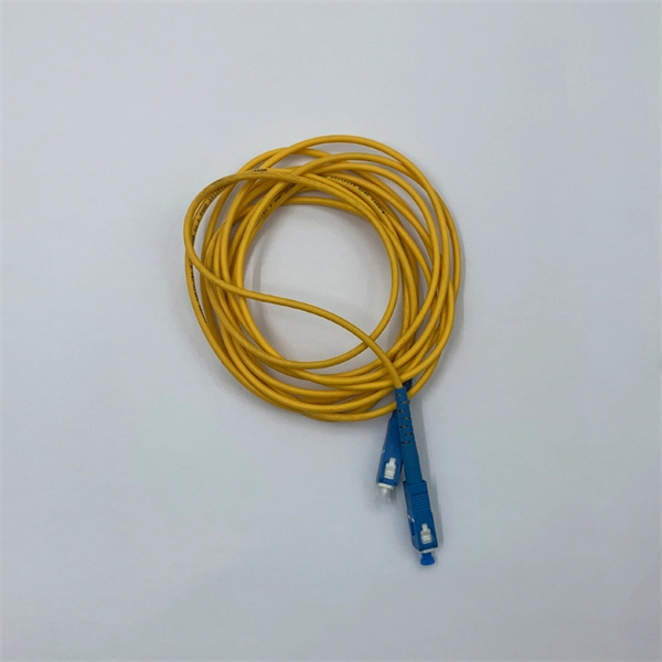
They are available in either riser or plenum flame rating, and have a 2. 0mm thick color-coded jacket. Standard patch cords are available in simple or duplex style, have matching connectors at each end and are available in 1, 2, 3, 5, and 10 meter lengths. Our fiber optic patch cords are factory terminated, inspected and tested to meet industry standards. Optical Fibre Cable Specifications:. Terminations at subscriber. simplex & duplex patch cords. SC, LC and FC connectors are PC m/ shown in cable with PVC jack ta ications Re shown in e 2. Fer hi e End Fac l ength≤1/2 nditions cked in one clear plastic bag. Test data sh uld be attached with each bag. Appropriate cushions should be used in the cardboard box. FTTX. af provides cutting-edge fiber optic technology and high-speed internet solutions across Afghanistan. Explore our reliable, scalable, and future-proof FTTX (Fiber to the X) networks designed for homes, businesses, and communities. Partner with Rahanet for seamless connectivity and innovation. Optical Fiber have reached internet speeds of over 100 Peta-bit per kilometer per second using fiber-optic communication. DSL technology will provide more bandwidth over existing copper telephone cabling running between a customer's premises and a Telco Central Office. One or both ends of the patch cord are equipped with standardized fiber optic connectors, and common interfaces include LC, SC, FC, ST, etc., which can be.
[PDF]
Discover the best prices and detailed specifications for Fibre Optic Cable Patch, with a total of 241 products. Visit BigGo now to find the cheapest deals, stock recommendations, and historical prices all in one place!. Get low-loss fiber patch cables & cords with various connector options that support fiber optic cabling up to 400G. Customized cables available. Pearlyond Technologies Singapore is an ISO9001 certified fiber optic patch cord cable manufacturer and fiber optic test equipment manufacturer since 2001,We supply OEM fiber optic products to world leading companies, our products include fiber optic patch cord,adapter,fiber optic attenuator. When choosing a fiber optic cable patch cord, it is essential to consider compatibility, performance, and application requirements. We offer fiber optic patch cords from Monoprice and Hubbell Premise Wiring in different connector and jacket types, lengths and modes of operation. These cables come equipped with UL rated optical fiber nonconductive rise (ONFR) and optical fiber nonconductive plenum (ONFP) cable jackets, and are.
[PDF]