
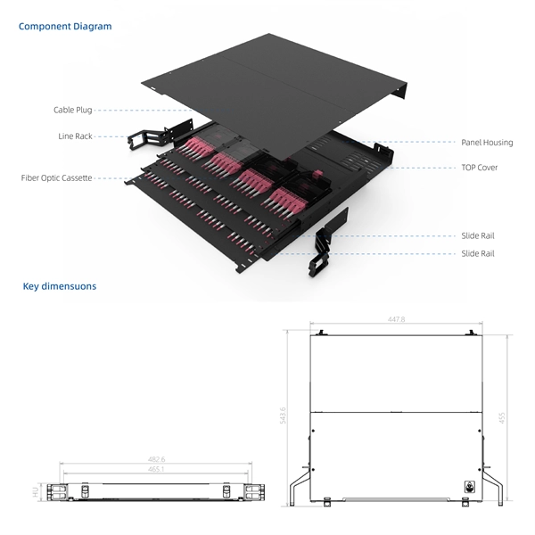
Dual ring topology is a network configuration that uses two concurrent rings of connections to link devices. This redundant network structure enhances reliability and provides a failover mechanism, ensuring high availability and network uptime. Device Level Ring (DLR) is a Layer 2 protocol that enables redundancy in a ring topology, providing fast network fault detection and reconfiguration for industrial networks. DLR is an EtherNet/IP™ protocol that is defined by the Open DeviceNet® Vendors' Association (ODVA). DLR network includes at. A fiber optic ring network is a physical or logical network topology where devices (usually switches) are connected in a closed-loop using fiber optic cables. Each node is connected to two other nodes, forming a ring-like structure. This design ensures data can travel in both directions. Data travels from node to node, with each node along the way handling every packet. Rings can be unidirectional, with all traffic. This document provides basic background information regarding adding ring redundancy in your wired Ethernet networks. It will explore the N-Tron proprietary protocol N-Ring and how it is a step up from IEEE Spanning Tree and Rapid Spanning Tree Protocol (STP, RSTP). DLR provides a means to detect, manage, and recover from single faults in a ring-based network. A DLR network includes the following types of ring nodes.
[PDF]

CWDM uses a multiplexer to divide the light wavelengths into different channels, each carrying a separate data stream. The channels are combined and transmitted over a single fibre optic cable. At the receiving end, a demultiplexer separates the wavelengths into the original. Coarse Wavelength Division Multiplexing (CWDM) is an optical networking technology that increases the bandwidth of existing networks. Learn all about CWDM, how it differs from DWDM, and whether a CWDM solution is right for your business's network. What is Coarse Wavelength Division Multiplexing?. In fiber-optic communications, wavelength-division multiplexing (WDM) is a technology which multiplexes a number of optical carrier signals onto a single optical fiber by using different wavelengths (i., colors) of laser light. This technique enables bidirectional communications over a. In that effort, what is CWDM Technology? CWDM (Coarse Wavelength Division Multiplexing) is a powerful fiber optic solution for high-speed, long-distance networking. It's one of several fiber optic cable choices, and it can fill many roles.
[PDF]

By using the online iPaper version of this price book you can directly link to the Grundfos Product Centre and Extranet. Centex Fluid Products Africa is an international leader in the design and manufacture of custom-built pumping packages & wastewater handling processing equipment for some of the most challenging environments around the globe. Centex is a master supplier of major product lines that includes. For all your mechanical seal needs visit our partner company First Seal. Schedule a date and time and we will come to you! Rain Curtain is our preferred approved installer for all your needs. Store Locator Plumblink Loyalty (VIP & PCC) Need help or advice?. DISCLAIMER: The information presented on this website is provided in good faith but is subject to change without prior notice. SINO Plant accepts no responsibility or liability for any errors or omissions. Designed for reliability and durability, our drainage and sewage pumps are built to handle the toughest tasks with ease. Whether you need to remove excess water from basements, construction sites, or sewage systems.
[PDF]

Global key players of Arrayed Waveguide Grating include NTT, NeoPhotonics, Accelink, Broadex Technologies, Agilecom, etc. The top five players hold a share over 64%. Asia-Pacific is the largest market, and has a share about 48%, followed by North America and Europe. Array waveguide gratings are important in telecommunications because they enable multiplexing and demultiplexing. Function: AWGs are used mainly for multiplexing (DWM). Operating. Arrayed waveguide gratings (AWGs) are passive optical devices based on planar lightwave circuits (PLCs) that spatially separate or combine light of different wavelengths. They utilize a phased array of waveguides with constant path length increments to create constructive interference for specific. Did you know that Arrayed Waveguide Gratings (AWGs) can multiplex and demultiplex over 100 different wavelengths of light on a single optical fiber? This makes them foundational to Dense Wavelength Division Multiplexing (DWDM), a technology that dramatically increases the bandwidth of optical. Arrayed waveguide gratings (AWG) are commonly used as optical (de)multiplexers in wavelength division multiplexed (WDM) systems. These devices are capable of multiplexing many wavelengths into a single optical fiber, thereby increasing the transmission capacity of optical networks considerably. At the transmission end, AWG arrayed. The AWG Arrayed Waveguide Gratings Module Market Size was valued at 799. 2 USD Million in 2024.
[PDF]

This precision cleaner quickly cleans the end faces of fiber optic connectors, while eliminating electrostatic charge, which can attract airborne contaminants to the end face. Talk to a knowledgeable OCC Expert that can find or customize a product to fit your specifications. . Chemtronics is the industry leader for fiber optic cleaning products, providing performance, convenience, time savings and cost savings. Cleaning fiber optic connectors is fast, easy and reliable with our highly engineered solvents, lint-free swabs, precision wipes, and cleaning platforms. AFL offers a complete selection of compact fiber optic cleaning kits for field cleaning of connector end-faces and splicer v-grooves. Fluke Networks Fiber Optic Cleaning Kits contain the best fiber optic cleaning tools and products to effectively remove the toughest contaminants in any optical fiber cable (OFC) network. 800-622-7711. Specialized Products provides a variety of optical fiber, end face and splice prep kits from leading fiber optics brands including Sticklers, Chemtronics, AFL and Fluke Networks. These kits are designed to include everything the fiber technician may need while working in the field.
[PDF]

This report lists the top Passive Optical Network (PON) Equipment companies based on the 2023 & 2024 market share reports. Mordor Intelligence expert advisors conducted extensive research and identified these brands to be the leaders in the Passive Optical Network . As a global technology powerhouse, Huawei Technologies Co. stands out for its robust portfolio in passive optical network solutions. The company integrates cutting-edge protocols and high-efficiency optical equipment, ensuring scalability for both urban and rural deployments. With a strong. A passive optical network (PON) is a fiber-optic telecommunications technology for delivering broadband network access to end-customers. Need. According to our (Global Info Research) latest study, the global Passive Optical Network Module market size was valued at US$ million in 2024 and is forecast to a readjusted size of USD million by 2031 with a CAGR of %during review period. The passive optical network module is a high-performance. With the global fiber optic cable market valued at $13. 92 billion and growing at 10. 46% annually, choosing from the best fiber optic manufacturers ensures your business infrastructure meets current demands and future scalability requirements. This Analysis is based on comprehensive primary and secondary research on the corporate strategies, financial and operational.
[PDF]

A virtual switch in Hyper-V is a software-based network switch that allows virtual machines to communicate with each other, with the host computer, and with external networks. When you first install the Hyper-V role on Windows Server, you can optionally create a virtual switch at the same time. To learn more about virtual switches, see Hyper-V Virtual Switch. It acts like a physical network switch but exists entirely in software, managing network traffic for your VMs. Hyper-V. This guide walks you through creating and configuring a virtual switch to connect your VMs to external, internal, or private networks. What is a Virtual Switch in Hyper-V? Be sure to check out our previous blog post for a step-by-step guide on installing the Hyper-V Server role on Windows Server. A network switch (also called switching hub, bridging hub, Ethernet switch, and—by the IEEE — MAC bridge) is networking hardware that connects devices on a computer network by using packet switching to receive and forward data to the destination device. A network switch is a multiport network. An Internal Virtual Switch in Hyper-V lets your virtual machines talk only to each other and your host PC. Open the Virtual Switch Manager and create a new Internal switch. Then assign this switch to the network adapter of each guest system. Depending on the type.
[PDF]

An optical network is a communication system that leverages light to convey information across distances, encoding data into rapid flashes of light instead of relying on electrical voltage changes. At the heart of this ecosystem lies the Optical Transport Network (OTN) — a framework defined by the ITU-T (notably G. 709) that has become the foundation for modern optical communications. This method allows engineers to manage the exponential growth in global data traffic generated by. A passive optical network (PON) is a system commonly used by telecommunications network providers that brings fiber optic cabling and signals all or most of the way to the end user. Depending on where the PON terminates, the system can be described as fiber to the curb, fiber to the building or. An Optical Transport Network (OTN) is a transmission network based on wavelength division multiplexing (WDM) technology. It is a specific type of transmission network that transmits data and manages it using optical signals. OTN is built on a series of protocols, including G. It is designed to provide a high-speed, scalable, and reliable infrastructure for the transmission of data between different network nodes. While there are many subtle differences, a clear distinction between active optical networking and PON topology is PON's use of a.
[PDF]
View inventory, pricing and order now for same day shipping!. View inventory, pricing and order now for same day shipping!. The beam splitter is an essential optical component that allows an incident light beam to be split into two or more partial beams. By using high-quality dielectric coatings on optical substrates, the beam splitter offers precise control over the ratio of reflected to transmitted light. This makes. Beam splitters are critical for managing optical power flow in a wide range of setups. Selecting the right component involves navigating trade-offs between power handling, polarization sensitivity, chromatic dispersion, and mechanical stability. A beam splitter is an optical device that separates. When working with lasers, it is often necessary to split a laser beam into two or more defined partial beams. There are a variety of beam splitters for these applications, with different advantages and disadvantages. Narrow down on the list of companies based on their location and capabilities. Bernhard Halle Nachfl. ZYGO specializes in providing large format, complex beamsplitters for use in aerospace.
[PDF]
148 (Grounding Conductor): Requires metallic junction boxes—and by extension, cabinet doors—to bond to ground using a designated grounding screw or clip. 28 (Box Materials): Metal boxes (like your cabinet) must be reliably grounded and bonded . NEC 250. A main bonding jumper is required to bond the service disconnect enclosure to the service neutral conductor [250. 28 (Box Materials): Metal boxes. All metal enclosures containing service conductors, such as meter socket enclosures and service disconnects, must be bonded to the grounding electrode system. 11 (D) is titled “Service Disconnecting Means” and requires a disconnecting means in compliance with Parts VI through VII of Article 230 to be provided to disconnect all ungrounded conductors of a power production source from the conductors of other systems. It is. Clearance: Electrical panels must be installed in a readily accessible area with a minimum clearance of 30 inches (762 mm) wide, 3 ft (36 inches or 914 mm) deep, and 6. 5 feet (≈ 2 meter) high in front of the panel. The panelboard's door (hinged cover) shall be able to be opened to a full 90°. Switchboards and panelboards are often called “the guts” of a premises wiring system. Article 408 covers the requirements for switchboards and panelboards that control power and lighting circuits (Fig.
[PDF]

Mount individual circuit breakers in the designated positions within the distribution box. Each breaker should match the current rating and type required for its specific circuit. Ensure proper connection to the busbars and secure mounting to prevent loosening over time. Correct wiring methods for circuit breakers within distribution boxes are fundamental to ensuring electrical safety and compliance with established codes. The distinction between 1P and 2P circuit breakers plays a pivotal role in determining the appropriate protection level for various circuits. This guide shows you how to organize circuit breaker wiring properly. You will learn to build a safe, efficient, and professional electrical system today. Circuit breaker wiring configurations involve organizing main switches, busbars. Circuit breakers, as important components in distribution boxes, can protect circuits from the effect of overload and short circuits. It serves as a central hub for distributing electricity throughout a building, ensuring that power is delivered safely and efficiently to all the required locations. We'll also look at whether it's good enough for your home, and what to do if your panel needs an upgrade. We want to help keep your home powered safely and. A breaker box, also known as a circuit breaker panel, is an essential component of any electrical system. To understand how a breaker box works, it is helpful to.
[PDF]

It is usually welded or threaded, and the two flanges are joined together by bolting them with gaskets to provide a seal, providing easy access to the piping system. A pigtail serves as a bridge between multiple conductors and a single terminal. These short wire segments solve space constraints in junction boxes by creating a central hub. Imagine three wires needing to. This is where the pigtail connector becomes an essential solution. A pigtail connector is a short length of wire with a factory-terminated connector on one end and bare, exposed wires on the other. It serves as a bridge, allowing technicians to repair specific connection points without disturbing. What is a Flange? Flanges are devices used to connect pipes, valves, pumps, fittings, and other equipment such as filters and pressure vessels. It ensures a secure connection by combining wires with a wire connector, like a twist-on connector or a wire nut, and then linking them to the intended terminal or fixture. Pigtails serve. Pigtail connections are most frequently used to ground a switch or electrical outlet and for electrical devices that need to connect to multiple circuit wires. They also come in handy to lengthen circuit wires that are too short to reach a device. It provides a plug-and-play repair solution that restores OEM fit, seal, and electrical reliability.
[PDF]

This comprehensive guide investigates the most frequent wire management challenges faced in real-world setups and demonstrates how the correct cable tray accessories may address them. Steel cable trays form the backbone of organized and efficient electrical wiring in industrial, commercial and infrastructure projects. Whether installed as stainless steel cable trays, these components offer durable and flexible solutions for routing cables safely. However, errors during the installation process can compromise the performance and durability of the trays. It also offers future-ready ideas, troubleshooting guidance, and useful suggestions to guarantee your cable systems. Cable trays are an essential part of electrical installations in buildings, providing support and protection for various cables and wires. However, like any other infrastructure, cable trays are prone to failures that can result in serious safety hazards, financial losses, and downtime. It is a safe way to route cables for easy maintenance and future upgrades. According to the 2005 National Electrical Code® (NEC), a cable tray system is " unit or assembly of units or sections and associated fittings forming a structural system used to securely fasten or support cables and raceways. " Cable trays support cable across open spans in the same manner that.
[PDF]