The usage agreement governs how much transmission capacity the customer subscribes to. The customer pays a fee for his subscription according to the grid tariff's capacity fee. The capacity fee shall cover t.
[PDF]

A 1U server rack measures exactly 1. 45 mm) in height and fits standard 19-inch racks. For example, a typical full-size rack cage is 42U high, while equipment is typically 1U, 2U, 3U, or 4U high. The rack unit size is based on a standard rack specification as defined in EIA -310. The Eurocard specifies a standard rack unit as the unit of height; it also defines a similar unit. U (rack unit, RU) is a unit of equipment height in a 19" rack. Important: U describes height only, but a server's real "capabilities" are also determined by chassis depth, internal layout, airflow, rails, power, and expansion (PCIe/risers, NVMe. Originally defined by the EIA-310 standard, the rack specifies a front panel width of 19 inches (482. 6 mm), allowing different hardware from various manufacturers to fit in the same enclosure. The unit calculator below can convert rack U's into cm, inches and feet. You'll get the precise, standardized dimensions of a 1U server rack unit — including height (1. 45 mm), width (19″ / 48. This three hole grouping is known as a rack unit (RU) or “U”.
[PDF]

DFM in optical design refers to the process of designing optical components and systems that are manufacturable, testable, and inspectable. The importance of DFM lies in its ability to reduce production costs, improve product quality, and accelerate time-to-market. The SPIE Digital Library's coverage of design for manufacturability (DFM) predominantly centers on semiconductor and optical system manufacturing. The content heavily emphasizes photolithography-related DFM, detailing techniques for optimizing mask designs, optical proximity correction, and. Design for manufacturability (DFM) is a critical first step in the development of any optical component. In the context of optics, DFM involves optimizing the design of optical components and systems to minimize production costs, reduce. Optical assembly manufacturing combines precision components such as lenses, prisms, mirrors, and other components that must perform in demanding environments. Taking complex optical systems from simulation into production involves meeting a range of mechanical, functional, and other requirements. Today, we are expanding my very first blogpost from 2020 and discussing the concept of Design for Manufacturability (DFM). In this article, we explore why DFM matters and how key design aspects influence the success of plastic optics. Understand the Limitations of Injection Molding.
[PDF]

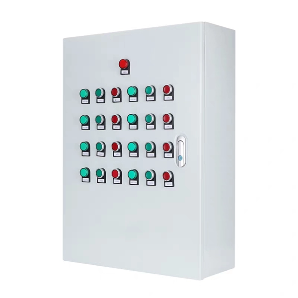
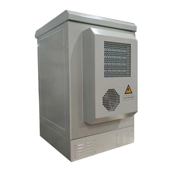
The purpose of the present invention is to provide an explosion-proof and flame-retardant distribution box, which has good explosion-proof and flame-retardant effect, strong impact resistance, is not easy to disperse, and has reliable safety performance. Flameproof enclosure (Ex d IIB+H2), which can be used as feed distribution equipment in control and distribution system (such as distribution box, switch box of main circuit, control box, terminal box or motor starting box etc. ) ·Enclosure: stainless steel. Equipped with specialized hinge. Substructure (use SSS=) and similarity (use ~) searches are limited to one per search at the top-level AND condition. Exact searches can be used multiple times throughout the search query. Searching by SMILES or InChi key requires no special syntax. To search by SMARTS, use SMARTS=. To search for. REV. Durable Hexlon Explosion Proof Distribution Boxes and Electrical Enclosures, IECEx and ATEX certified for Zone 1 and Zone 2. Design explosion-proof distribution box (control box) to meet equipment category and group requirements; b. They include fully modular low- and medium-voltage Ex-e, Ex-d, and Ex-p solution components, from Switchgear, Splitter Boxes, Junction Boxes, Ring Main Units, Power Supply, Motor.
[PDF]

Home and business fiber optics projects typically range from a few hundred to several thousand dollars, depending on run length, fiber type, and labor needs. The main cost drivers are materials, installation time, and environmental factors that affect trenching, conduit, and terminations. Commercial building installations with 100-200 network drops generally range from $15,000 to $30,000. Single-mode fiber costs less per foot than multimode fiber, but it requires more. What is Fiber optic network design? Fiber optic network design involves the planning, routing, and drafting of Fiber cable layouts to support high-speed data transmission. It includes detailed mapping of backbone, distribution, and drop connections for FTTH, FTTP, FTTx, and enterprise networks. Fiber optic network design refers to the specialized processes leading to a successful installation and operation of a fiber optic network. It includes first determining the type of communication system (s) which will be carried over the network, the geographic layout (premises, campus, outside. According to ResearchAndMarkets, the global market for fiber optics was estimated at $5. 8 billion in 2022 and is expected to reach $11. This is the dominant broadband access technology across half of OECD countries today. The price landscape varies from basic drop cables to enterprise backbone runs, with per foot and per reel pricing common in estimates. This guide presents cost ranges.
[PDF]
Standard Price refers to the predetermined cost of a good or service, often used in cost accounting to measure performance and budget. The standard price of fuel is a tool that was created by Department of Defense fiscal managers to insulate the military services from the normal ups and downs of the fuel marketplace. It provides the military services and the Office of the Secretary of Defense with budget stability despite the. This chapter provides the policy to guide budget formulation and execution for Supply Management Activities (SMA) of the Defense Working Capital Fund (DWCF) and is applicable to all DoD working capital funds. Title 10, United States Code, section 2208 (10 U. Think of it as the benchmark cost you expect under normal operating conditions. The concept of Standard Price has its roots in the early 20th century when industrialization demanded more rigorous and systematic methods for cost control and. The standard price is the price for a semi-finished or finished product, obtained on the basis of a product calculation. It is a fixed price that does not take into account the movement of goods or the recording (booking) of the invoice and is used to price the goods. Price type assigned to. The chart has 1 Y axis displaying values. Average price data (in U. dollars), selected items Bananas, per lb. Oranges, Navel, per lb. Electricity per KWH Eggs, grade A, large.
[PDF]
3‑E “Optical Fiber Cabling and Components Standard” was developed by the TIA TR‑42. 11 Optical Fiber Systems Subcommittee and published in September, 2022. Fiber optic patch cables are ideal for supporting high speed telecommunication network fiber applications. They are manufactured and tested in compliance with TIA 604 (FOCIS), IEC 61754 and YD/T industry standards. OM1, OM2, OM3, OM4, OM5 or OS2 fiber types are available to meet the demand of. Leviton fiber optic patch cords meet or exceed industry standards to make sure you get the performance you expect. They are available in multimode (OM1, OM3, OM4, OM5) and single-mode (OS2) fiber types, with a range of SC, ST and LC connectors. These standards are very important. They make sure patch cords work well, are safe, and can connect with other equipment. The high-quality fiber optic. ANSI/TIA‑568.
[PDF]

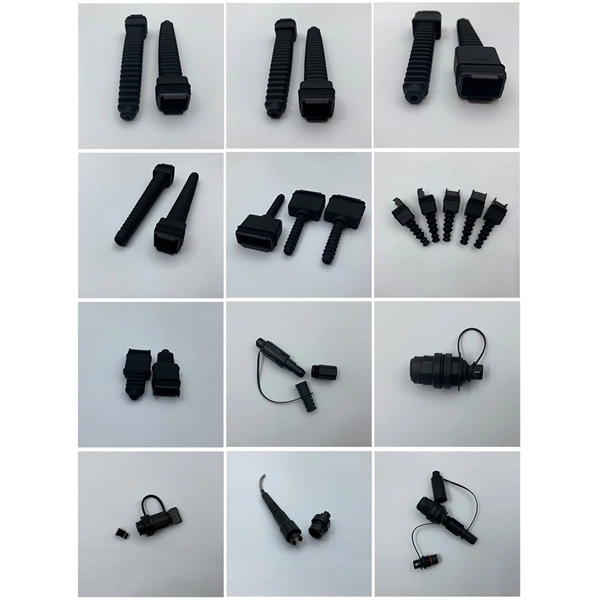
The FC/PC (Physical Contact) and FC/APC (Angled Physical Contact) fiber optic connectors are standardized under TIA EIA/TIA-604-4 and IEC 61754-13. ABSTRACT: This standard describes the point-to-point physical interface portions of Fibre Channel serial electrical and optical link variants that support the higher level Fibre Channel protocols includ-ing FC-FS, HIPPI, IPI, SCSI and others. This standard is recommended for new implementations but. Fiber connector types LC, SC, FC, ST, MTP, and MPO are widely used in past and present. What are the differences between them? Who is the most popular one? Find the answer in the article. What is a Fiber Connector? The optical fiber connector is a kind of detachable passive optical component used. An optical fiber connector is a device used to link optical fibers, facilitating the efficient transmission of light signals. An optical fiber connector enables quicker connection and disconnection than splicing. Unlike fiber splicing, which is permanent, connectors allow for easy connection and disconnection of cables, making them ideal for maintenance and flexibility in. Understanding fiber connector types—SC/APC, SC/PC, LC/UPC, LC/APC, ST/PC, FC/PC, and FC/APC—is essential for selecting the right interface for your application. Each type varies by shape, polish (APC, PC, or UPC), and return loss performance, which affect PC, UPC, and APC Polish Styles: What's the.
[PDF]
In normal operating conditions the power consumption of a load is sometimes less than that indicated as its nominal power rating, a fairly common occurrence that justifies the application of an utilization facto.
[PDF]

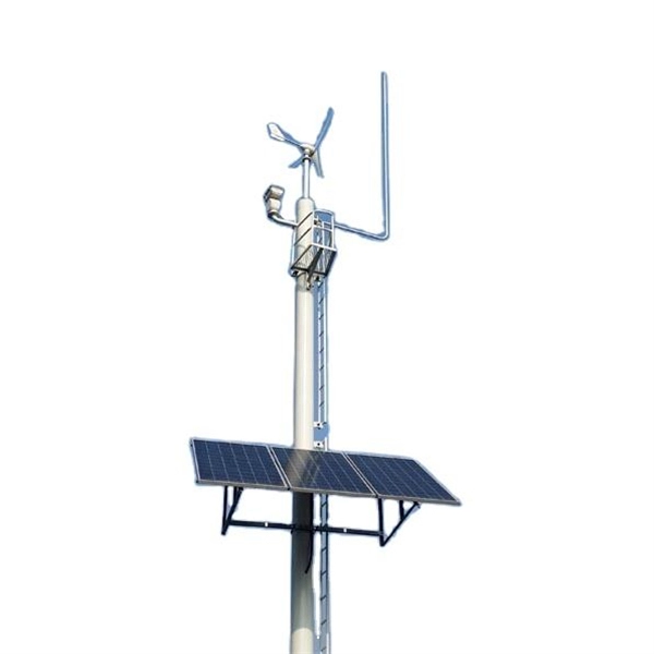
This Code consists of the introduction, definitions, grounding rules, lists of referenced and bibliographic documents, and Parts 1, 2, 3, and 4 of the 2023 Edition of the National Electrical Safety Code. The Institute of Electrical and Electronics Engineers, Inc. 3 Park Avenue, New York, NY. Climbing Space is an unobstructed, vertical space along the side or corner of the pole. In gen-eral, it consists of an imaginary box, 30-inches square, extending at least 40 inches above the highest communications cable or other facility and 40 inches below the lowest communications cable or other. The Fiber Optic Association, Inc. (FOA) was founded in 1995 to help develop the workforce to build the fiber optic networks to support a rapid expansion in communications and the Internet. The charter of the FOA was to promote professionalism in fiber optics through education, certification, and. There are a number of ways of finding out more about cabling standards. You can buy a complete copy of the EIA/TIA or ISO/IEC standards which can be very expensive and wade through page after page of standards language. You can also get catalogs and/or visit the websites of a number of cabling. to n utral comm.
[PDF]

Practice good wiring: secure grounding, neat cable management, proper insulation, and correct wire gauge and breaker size. Include protection devices like breakers, fuses, and surge protectors—each circuit should have its own protection. Comply with standards: Follow NEC, IEC . In this video, we'll walk you through the process of wiring a home distribution box with a detailed connection diagram. Whether you're an electrician or a DIY enthusiast, this guide will help you understand the basics of home electrical distribution. more Welcome to our. A distribution board (also known as a service panel or breaker box) is a centralized collection of circuit breakers, fuses, and/or relays used to control and protect the wiring in a home. The diagram of the distribution board's wiring shows exactly how each circuit is wired and connected. Choose the right box based on environment (indoor/outdoor), load capacity, and durability. Check for proper IP/NEMA ratings and material quality. Ensure safe placement: install in. The term “four wires” refers to three live wires and one neutral wire, designated as A|B|C|N|, with N representing the ground wire. The three live wires should be connected to the upper entry of the main switch in the explosion-proof distribution box, and the neutral wire should be directly.
[PDF]

This AutoCAD DWG file includes a complete Single Line Diagram (SLD) of a Distribution Board, showing circuit breakers, wiring connections, and load distribution for lighting, power, and mechanical systems. An electrical panel box, also known as a breaker box or a distribution board, is a crucial component of any electrical system. It serves as a central hub for distributing electricity throughout a building, ensuring that power is delivered safely and efficiently to all the required locations. Whether you're an electrician or a DIY enthusiast, this guide will help you understand the basics of home electrical distribution. What is Distribution Board? Distribution board. Welcome to our channel @Electricalgenius In this video, we'll take you through a detailed step-by-step guide on wiring a home distribution DB (Distribution Board) box. A distribution board (also known as a service panel or breaker box) is a centralized collection of circuit breakers, fuses, and/or relays used to control and protect the wiring in a home. The diagram. To understand how a breaker box works, it is helpful to have a wiring diagram that shows the connections between the various components. At the heart of a breaker box is the main breaker, which controls the flow of electricity from the utility into the building. This breaker is connected to a.
[PDF]
What does it take to make an effective explosion-proof junction box or cabinet? An incredible mechanical engineering design is what you need. Design for such enclosures and storage boxes differ with each m.
[PDF]