An optical power meter (OPM) is a device used to measure the power in an signal. The term usually refers to a device for testing average power in systems. Other general purpose light power measuring devices are usually called,, power meters (can be sensors or ), or lux meters. A typical optical power meter consists of a , measuring and display. The sens.
[PDF]

Optical power meters can measure the power of both single-mode and multimode fibers. In single-mode fiber, the rays travel down its entire length without any internal reflection at all. In multimode fiber, multiple rays enter at different angles and possibly have different wavelengths. An optical power meter (OPM) is a device used to measure the power in an optical signal. The term usually refers to a device for testing average power in fiber optic systems. The term "optical power meter" may sound generic, but in popular usage, it specifically implies a fiber optic power meter. For light power measurements outside the field of. Optical loss is measured in “dB” which is a relative measurement, while absolute optical power is measured in “dBm,” which is dB relative to 1mw optical power Loss is a negative number (like –3. It details the main components, including sensor heads and display units, and explains the two primary sensor technologies: robust thermal sensors for high powers and. The OMM-6810B is a power and wavelength meter capable of simultaneously measuring the optical power and wavelength of a laser source. A wide variety of measurement heads cover wavelength ranges from 400 to 1650 nm for power ranges of up to +40dBm or 10W. Fiber optic connections form the backbone of modern data infrastructure, yet even a small speck of dust can render a link completely.
[PDF]

The mechanical dimensions of an optical power sensor can be quite relevant for applications, e.g. when a sensor needs to be temporarily inserted into some beam path, where there is little available space. There are some very flat hand-he. The mechanical dimensions of an optical power sensor can be quite relevant for applications, e.g. when a sensor needs to be temporarily inserted into some beam path, where there is little available space. There are some very flat hand-held sensors, mostly based on photodiodes, which require quite little space. Thermal power sensors are intrinsically relatively slow – particularly those for high powers, where the thermal capacity of the sensor is tentatively higher. Typical response times are of the order of 0.2 s to 2 s. Even photodiode-based power meters are normally not made very fast, since one could anyway not read a display which is updated e.g. 10. Power meters require some electrical power, which may either be provided with an external power supply or with batteries (which are normally rechargeable). Battery-powered operation is of course convenient by eliminating another cable enter the requirement of a nearby power socket, but on the other hand the need for regular recharging can also be i.
[PDF]

Enter the optical input power, additional loss, and select a PLC splitter or tap ratio to estimate the output power (in dBm) on each branch. Optical splitters play a crucial role in Fiber to the Home (FTTH) Passive Optical Network (PON) systems, efficiently distributing a single optical signal to multiple destinations. The split ratio and insertion loss are two key parameters defining their performance. A deeper understanding of these. In the backbone of modern Fiber-to-the-Home (FTTH) networks, optical splitters serve as the unsung heroes that enable cost-efficient connectivity for millions of subscribers. By dividing a single optical signal from a central Optical Line Terminal (OLT) into multiple outputs for Optical Network. Optical splitters play an important role in FTTH PON networks where a single optical input is split into multiple output, thus allowing a single PON interface to be shared among many subscribers. The optical splitters have no active electronics and don't require any power to operate. The optical power at the input is split to the outputs at an even ratio: Optical splitter modules use passive optical circuits. The modules fit the OG3-FR frame but draw no.
[PDF]

The receiver of an optical module has an overload point. Therefore, an optical attenuator is required to reduce the optical power. By introducing a precise and constant amount of optical loss, it ensures that the incoming signal remains within the optimal operating range of the receiver. A. Average optical power refers to the optical power outputted by the optical module's transmitter under normal working conditions, which can be understood as the intensity of light. The transmitted optical power is related to the proportion of "1"s in the transmitted data signal; the more "1"s, the. The receiver of an optical module has an overload point. If the optical power received by the receiver is excessively high, the optical module will be burnt. In addition, during signal transmission in a WDM system, the. 📦 For purchasing, use the RP Photonics Buyer's Guide for optical attenuators. It provides an expert-curated supplier directory, buyer-focused technical background information, and structured selection criteria to support professional procurement decisions. Optical attenuators are devices that. An optical attenuator, or fiber optic attenuator, is a device used to reduce the power level of an optical signal, either in free space or in an optical fiber. Optical internetworks are data networks composed of routers and data.
[PDF]
Commonly, a power meter on its own is used to measure absolute optical power, or used with a matched light source to measure loss. When combined with a light source, the instrument is called an Optical Loss Test Set, or OLTS, typically used to measure optical power and end-to-end optical loss.OverviewAn optical power meter (OPM) is a device used to measure the power in an signal. The term usually refers to a device for testing average power in systems. Other general purpose light power measuring. The major types are (Si), (Ge) and (InGaAs). Additionally, these may be used with attenuating elements for high optical power testing, or wavelengt. A typical OPM is linear from about 0 dBm (1 milli Watt) to about -50 dBm (10 nano Watt), although the display range may be larger. Above 0 dBm is considered "high power", and specially adapted units may measure u.
[PDF]
An increasingly common special-purpose OPM, commonly called a "PON Power Meter" is designed to hook into a live PON () circuit, and simultaneously test the optical power in different directions and wavelengths. This unit is essentially a triple power meter, with a collection of wavelength filters and optical couplers. Proper calibration is complicated by the varying duty cycle of the measured optical signals. It may have a simple pass/ fail display, to facilitate easy use by operators wit.
[PDF]
Multimode fiber optic cable has a larger core, typically 50 or 62. 5 microns that enables multiple light modes to be propagated. Because of this, more data can pass through the multimode fiber core at a given time. The maximum transmission distance for MMF cable is around 550m at the speed of. Multimode Fiber (MMF) has a core diameter, typically 50–100 micrometers, has ability to transfer multiple modes of light through the fiber core, uses lower-cost electronics (LED, VCSEL) operates at the 850 nm and 1300 nm wavelength and is used for short distance interconnections (up to 550m). This Applications Engineering Note (AE Note) discusses the criteria for properly selecting the optimal multimode fiber (MMF) for enterprise applications. Both fiber types play essential roles in today's optical.
[PDF]

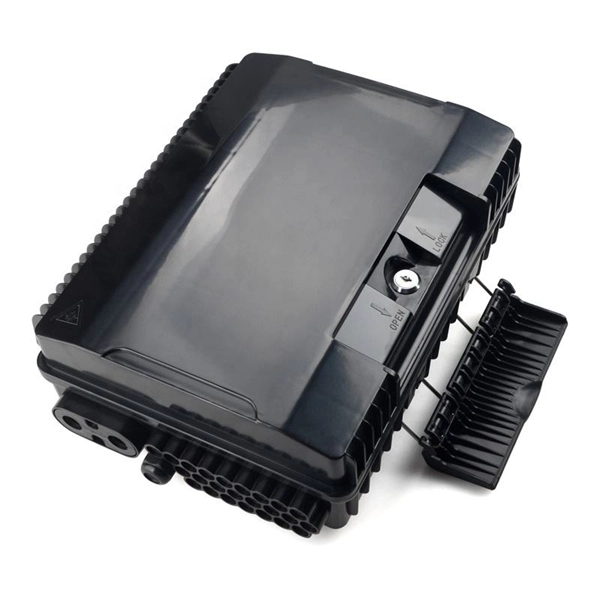
A Fiber optic cap type splice box is a protective enclosure designed to house and organize fiber optic splices. It typically features a dome or cap-style closure that provides a sealed environment for fiber joints, protecting them from external conditions. As fiber optic networks continue to expand across urban, rural, and industrial environments, the reliability of connection points becomes. The cap-type splice box is mainly designed for laying optical cables in overhead and tunnels. It does not meet the waterproof requirements of the regulations when used in direct-buried lines, but the moisture-proof effect in lines is better. According to regulations, the open type and other three. The types of optical cable splice boxes can be divided into cap-type optical cable joint boxes and horizontal optical cable joint boxes according to the shape and structure. According to. Grandway's fiber optic closure provides a high density wall mounted or pole mounted solution for next generation networks, which aims to provide and manage fiber splitters in a limited space. It is designed for FTTH (Fiber to the Home) or FTTB (Fiber to the Building) with protective housing for all. Briefly explain how fiber splice closures are critical for network protection and performance optimization. Introduce that choosing between dome (cap-style) and horizontal (in-line) closures depends on specific project requirements. Understanding Fiber Splice Closure Types 1.
[PDF]

Connect the red wire to the copper wire with the red color bar of the optical/electrical composite cable, and connect the black wire to the other copper wire of the optical/electrical composite cable. Then press and secure the crimp tube. Ensure that no copper. The composite fiber optic cable is a type of cable that combines both fiber optic and copper conductors within a single cable sheath. This hybrid construction allows for the simultaneous transmission of data using fiber optics and electrical power or additional data using copper conductors. How to Use the Composite Fiber Optic Cable? To begin, you need to gather all the accessories and equipment required: 1. Waterproof Industrial-Grade Fiber PoE Media Converter Compatible with the IEEE802. Cut the cable along the center and pull one copper cable on the left and right sides to the position shown in the figure to expose the optical fiber. Whether you're a seasoned technician or a beginner, this guide has something for everyone. more In this video, we'll walk you. In a previous blog, we covered what to do when you need to connect a device that is located beyond the 100-meter distance requirement and described four ways to address the problem—a new TR, the use of an extender device, extended-reach copper cable and fiber. This article will guide you through the necessary tools, materials, and methods on how to connect fiber optic cables effectively.
[PDF]
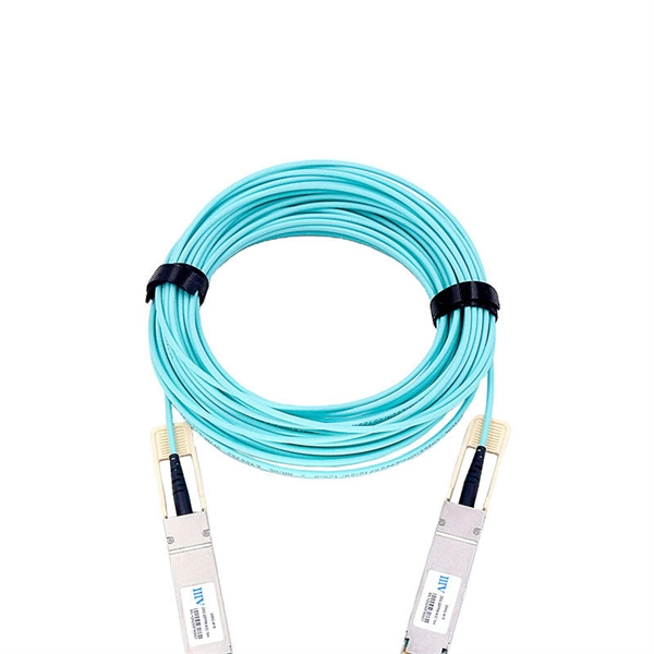
Locate Fiber Optic Cables suppliers, manufacturers & distributors in Sweden. Interactive map of Sweden provided. The Swedish Microwave fiber cables are made as ruggedized cables with narrow bend radius and very good performance to fit together with all our RF over Fiber products. They are all single-mode fiber cables and IP 65 classed when mated. We can offer fiber cables as Q-ODC to Q-ODC cables or as patch. Nexans' range of fiber optic cables includes products intended for data and telecommunications as well as industrial applications. Their product range includes robust cables suitable for various environments, ensuring exceptional performance and fire. Ahlsell helps you find quality cables for telecom, data, and other cable installation. Our assortment provides all kinds of cables, whether you work outdoors or indoors. We have connection cables, control cables, and power cables. Optical Cable Corporation (OCC) is a leading cable manufacturer of secondary buffered fiber cable and is based in Roanoke, USA, where production takes place. We are proud of the close cooperation that has developed between Micropol and OCC. 100G QSFP28 Active Optical Cable Product Overview: The 100G QSFP28 Active Optical Cable (AOC) is a state-of-the-art solution designed to meet the high-speed data transmission requirements of modern data centers, high-performance computing networks, and enterprise settings. This cable is engineered.
[PDF]

You can plug various networking devices into an SFP (Small Form-factor Pluggable) port, such as fiber optic transceivers, gigabit Ethernet modules, and SFP modules. These can include devices such as switches, routers, network interface cards, and media converters. SFP (Small Form-factor Pluggable) is a compact, hot-pluggable network interface module used to connect network devices (switches, routers, firewalls) to fiber optic or copper cables. An SFP interface on networking hardware is a modular slot for a media-specific transceiver, such as for a fiber-optic cable or a copper. Optical transceivers are compact, hot-pluggable devices that convert electrical signals into optical signals, enabling high-speed data transmission across switches, routers, and other networking equipment. Transceiver compatibility is a key concern in enterprise network deployments. Can the sfp interface be plugged. SFP modules function by converting electrical signals from a switch or router into optical or copper signals that can travel through various transmission media. They are inserted into SFP ports found on networking hardware and come in multiple variants to support different cable types, distances.
[PDF]
A bundle fiber optic cable refers to a type of optical fiber cable where multiple individual fibers are grouped or bundled together within the same outer sheath. Stranded fiber optic cable is a loose tube made of high-modulus plastic by adding colored optical fiber and ointment at the same time, and the optical fiber can move in the tube. Different loose tubes are twisted along the central reinforcing core to make the cable core. Instead of having individual round cables, ribbon cables have several fibers laid out side by side, typically in a flat and compact. 📦 For purchasing, use the RP Photonics Buyer's Guide for fiber bundles. It provides an expert-curated supplier directory, buyer-focused technical background information, and structured selection criteria to support professional procurement decisions. What is a Fiber Bundle? For some applications. Fiber optics, or optical fibers, are long, thin strands of carefully drawn glass about the diameter of a human hair. These strands are arranged in bundles called fiber optic cables. We rely on them to transmit light signals over long distances. This article is going to introduce fiber optic bundles, and it is configuration examples, benefits, and applications. Because the cross-section of a single optical fiber is too thin, it is not suitable for transmitting images or light, so this function is achieved by.
[PDF]


