High-definition temperature sensing based on the natural Rayleigh backscatter in optical fiber delivers a virtually continuous line of temperature measurements with sub-millimeter spatial resolution. 1. Map temperat.
[PDF]

When it comes to testing fiber optic cables, a Visual Fault Locator (VFL) is an essential tool in your toolkit. A VFL is used to detect faults, breaks, or bends in fiber optic cables by emitting a bright red light that is visible even through the fiber's jacket. Let's dive into everything you need to know about mastering VFLs. In the. Finding a break in a fiber optic cable can be challenging but is essential for maintaining a stable network. Common Indicators of a Cable Break Signal. Here Kingfisher's experienced engineers share their experience in best practices and procedures for fiber optic testing related mostly to installation and maintenance. We hope that by sharing our knowledge, we will help grow our industry. Please enjoy & pass on these notes. The following are key methods and techniques used for optical fiber cable line failure positioning: Visual Inspection: Perform a visual inspection of the. Locating faults in fiber optic cables requires specialized tools and techniques. Look for dirt, scratches, or damage on the connectors. Clean. To ensure the quality and continuity of fiber optic services, it is essential to identify and locate fiber optic cable faults as quickly and accurately as possible. In this article, you will learn about some of the common methods and tools for fiber optic testing and troubleshooting.
[PDF]

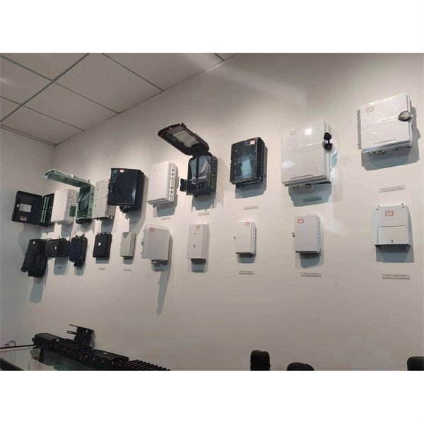
Mount individual circuit breakers in the designated positions within the distribution box. Each breaker should match the current rating and type required for its specific circuit. Ensure proper connection to the busbars and secure mounting to prevent loosening over time. When opening the distribution box, several different brands of circuit breakers are installed inside. It seems that the sizes match and the installation is fine, and this. The feeder amp rating is sized based on the sum of the amp rating of the largest branch protective device plus the full-load currents of the other loads. This value is added to the full load currents of the. Finding the right circuit breaker for your electrical panel is crucial to ensure safety, performance, and code compliance. Not all breakers are interchangeable across different panel brands – each manufacturer designs its breakers and panels as a matched system. Using a breaker that isn't made or. In industrial power distribution systems, cable distribution boxes (also known as power distributor boxes, distribution electrical boxes, or electrical power distribution boxes) are the core hub of power transmission, branching, and protection. You lower the chance of circuits getting too hot or overloaded when you pick the right box for your needs. A single circuit breaker installation mistake can cost your facility thousands in downtime, equipment damage, or worse—put lives at risk.
[PDF]

The setting value can be finely adjusted manually. Press and hold the and buttons simultaneously for three seconds. Use the to select "rSt", then press the button. Settings are summarized in "Basic" and "Advanced" categories. Providing quick solutions for every scenario. In cases where more advanced features or troubleshooting is necessary, the "Advanced". This video covers how to setup and configure the Wenglor OPT2041 Fiber Optic Sensor from AutomationDirect. **Please check our website for our most up-to-date product pricing and availability. This sensor works with both Plastic and Glass fibers. Keep in mind that the color and reflectivity of the. The KEYENCE FS-N10 Fiber Sensor is a versatile and reliable device used for detecting objects. This sensor uses a fiber optic cable to transmit and receive light, allowing for accurate and precise detection in a variety of applications. The FS-N10 series is capable of detecting objects of different. Fiber optic Sensors; How to program Keyence Fiber optics amplifier from EMI Documentation can be found here:. This is the SET push button; this is used to calibrate the sensitivity.
[PDF]

RCCBs (Residual Current Circuit Breakers) should be installed in key areas of your home's electrical system for maximum safety. The best place to install an RCCB is in the distribution board (DB box), which controls the electrical circuits throughout your home. This location ensures that the RCCB protects the entire electrical system by monitoring the current flow throughout. For added protection, you can also. A residual-current device (RCD), residual-current circuit breaker (RCCB) or ground fault circuit interrupter (GFCI) is an electrical safety device, more specifically a form of Earth-leakage circuit breaker, that interrupts an electrical circuit when the current passing through line and neutral. The primary function of an RCD is to monitor the electrical current flowing in a circuit and quickly disconnect the power supply if it detects an imbalance current (leakage of current to ground) between the live and neutral conductors. An RCD is essentially a current-operated ELCB and is commonly. RCCB Definition: A Residual Current Circuit Breaker (RCCB) is defined as a safety device that detects and interrupts a circuit when there is a leakage current to the ground. It can swiftly disconnect the circuit when a fault current happens and prevent wiring damage. In this article, we explain what an RCBO is and how it.
[PDF]

This video provides a detailed walkthrough of designing and simulating an automatic light control system using Light-Dependent Resistor (LDR) and Triac in Proteus Software. Last updated on 13 August 2025 by Admin-Lavi Leave a Comment This article talks about Light Controlled Switch Circuit using IC LM311 and LDR. It simple and very useful and it feel light change near it. We find this circuit in many place like automatic light, street lamp and security system. Main. ABB's Control Room offering includes a comprehensive range of solutions designed to optimize the operator workspace for critical 24/7 processes across various industries. The project demonstrates how to create a smart lighting system that turns on/off automatically based. more This video. The Intro Screen changes as you play with it. It has a Play Area and a Control Area. A Construction Area creates a building space for components added from a Circuit Component Toolbox. Build and navigate your circuits there. If Voltmeters and Ammeters are out of the toolbox, you can take. Common sense schematics let you name a node "+5V" and know that the simulator will do the right thing automatically, keeping your schematics compact and elegant. This circuit activates or deactivates connected loads, such as LEDs or light bulbs, based on ambient light levels.
[PDF]
A distribution box, or DB box, is a circuit breaker enclosure. It is a vital part and central hub of any electrical system. The hub distributes electrical power from a single input source to various circuits throughout a building. A distribution box, also known as a power distribution box or electrical distribution box, is used to distribute electrical power safely to multiple circuits. Distribution. A distribution boxes is an essential device that manages the safe and efficient flow of electrical power throughout different areas of a building or facility. Today, electrical systems are essential for homes and industries. It is widely employed in residential, commercial and industrial set-ups for circuit control and protection. By knowing their great.
[PDF]

In this guide, we'll break down the essentials, explore different wiring configurations, and provide you with practical tips to get your sensors up and running smoothly. So, grab your tools, and let's get started! Before we jump into wiring diagrams, let's quickly recap what fiber optic sensors are. working principle: Fiber optic sensors use the propagation characteristics of light to detect or measure various physical and chemical quantities. Here are some basic working principles of fiber optic sensors: Propagation of Light: An optical fiber consists of two parts: a core (the central part of. A Fiber Sensor is a type of Photoelectric Sensor that enables detection of objects in narrow locations by transmitting light from a Fiber Amplifier Unit with a Fiber Unit. Detection in Narrow Locations The small sensing section and flexible Fiber Unit cable enable a Fiber Sensor to. Click to download the ODiSI Fiber Optic Sensor Installation Guide. The following instructional videos explain how to install, configure, and calibrate the FiberPatrol FP400 fiber optic fence-mounted intrusion detection sensor. Copyright © 2026 Senstar Corporation. Legal | Accessibility. Surprisingly Stable Detection with Your Finger tip. Exceptionally easy operation and stabilizing technology reduce maintenance cost. If you Login / Signup, you can download the PDF of the Manual. Please note some product models not sold in Singapore may be included in the following manual (s) for.
[PDF]
A fiber-optic sensor is a that uses either as the sensing element ("intrinsic sensors"), or as a means of relaying signals from a remote sensor to the electronics that process the signals ("extrinsic sensors"). Fibers have many uses in. Depending on the application, fiber may be used because of its small size, or because no is needed at the remote location, or because many sensors can be along the length of a fiber by using light wavelength shift for.
[PDF]

FOCS systems can measure currents up to 700 kA. They offer a practical alternative to traditional Hall-effect sensors, using a lightweight, clamp-on design that allows installation without opening bus bars — reducing time and complexity. A fiber-optic current sensor (FOCS) is a device designed to measure direct current. Utilizing a single-ended optical fiber wrapped around the current conductor, FOCS exploits the magneto-optic effect (Faraday effect). The result is exceptional accuracy and reliability. Based on the magneto-optic effect, FOCS can measure uni- or bidirectional DC ering signal disturbance immunity available for complex industrial processes. It is unaffected by stray magnetic fields at the plant, s. The FS205 is a high precision DC high current measurement device based on the Faraday Magneto-optical Effect and the Ampere Loop Theorem. The sensing optical fiber is fixedly mounted on the high current busbar through a skeleton and forms a closed optical fiber loop. They are immune to electromagnetic interference (EMI) and do not suffer from magnetic saturation, which improves accuracy, simplifies installation, and enables reliable digital. A fiberoptic sensor that uses diverse fiber units to support various applications in virtually any environment. These are reliable and easy-to-use devices that have high power, can automatically adjust to real-time conditions, and have a straightforward display that eliminates any guesswork.
[PDF]
The numerical aperture (NA) of an optical fiber is the number that defines the range of angles over which the fiber can receive, guide, and release light rays. A2=2m,300Vcable F4=pigtailw/4-pinDCmicroQD G3=pigtailw/3-pinACmicroQD Y4=pigtailw/4-pinDCpicoQD X4=custom4-pinconnector Notallvariationsavailable. Contactfactoryforavailability. Has simple set-up and configuration. The D10 Expert detects the web if it droops into the sensor's beam because the tension is too loose; the D10 then sends a signal to the controller to adjust. Product will be phased out and can be ordered until 2026-11-30. WLL80P-22T6Y1DZA71Z1Z1 Sensing range max. However, sensors based on fiber‐optics have been developed rapidly because of their excellent sensing performances and capability to function in remote and harsh environments. The usage of fiber‐optic sensors has flourished in many fields over the past 30 years due to the fiber‐optic's inherent. A colour sensor is a type of "photoelectric sensor" which emits light from a transmitter, and then detects the light reflected back from the detection object with a receiver. Detection in Narrow Locations The small sensing section and flexible Fiber Unit cable enable a Fiber Sensor to detect.
[PDF]
The Fiber Optic Sensors market was valued at USD 2,560. 00 million in 2018, reached USD 3,547. Starting at USD 2. By 2035, it is projected to reach USD 6. 3% throughout the forecast period from 2026 to 2035. I need the full data tables. As per Market Research Future analysis, the Fiber Optic Sensor Market Size was estimated at 3. 08 USD Billion by 2035, exhibiting a compound annual growth rate (CAGR) of 10. 22% during the. Fiber optic communication relies on light waves, which are difficult to intercept or tamper with, making fiber optic sensors an attractive option for industries that require secure data transmission. I need the full data tables, segment breakdown, and competitive landscape for detailed regional analysis and. Global Fiber Optic Sensors Market Research Report By Type (Intrinsic, Extrinsic), By Component (Receiver, Transmitter, Fiber Optic Cable, Optical Amplifier), By End-User (Transportation, Medical, Defense, Industrial, Oil and Gas), By Region (North America, Europe, Asia Pacific, Latin America. Global Fiber-Optic Sensors Market Size By Type of Fiber-Optic Sensors (Intrinsic Fiber-Optic Sensors, Extrinsic Fiber-Optic Sensors), By Sensing Parameter (Temperature Sensors, Pressure Sensors), By Application Sector (Aerospace and Defence, Oil & Gas), By Technology (Fibre Bragg Grating.
[PDF]

Get price quotes for Fiber Bragg Grating. Contact suppliers directly with one click. Use this fiber Bragg gratings buying guide to compare major types, define selection criteria, and find suppliers: Professional purchasing of high-value photonics products is a substantial responsibility, where a structured decision-making process is essential. RP Photonics offers a lot of help: Get. Comparing fiber bragg grating sensor prices. How does 6W market outlook report help businesses in making decisions? 6W monitors the market across 60+ countries Globally, publishing an annual market outlook report that analyses trends, key drivers, Size, Volume, Revenue, opportunities, and market segments. All our Fiber Bragg Grating Arrays and Cable models are designed to make handling and deployment fast, easy and intuitive. Technica. Transmission spectrum for a sample FBG with center wavelength of 1546. 83nm and 90% reflectivity: Please note: the FBG is made on bare single mode fiber and has no steel tube or any other types of package. © 2024 CB Cabling Technologies Ltd.
[PDF]