Gisteren werden de website en de socials van Pon Equipment omgezet naar Zeppelin Equipment NL. Pon Equipment and Power Power transitioned into Zeppelin Holding Netherlands on November 3rd, 2025. The division was. Frankfurt, 11 December 2024 – Proventis Partners advised Zeppelin Group (Germany) on the acquisition of the sales and service of Caterpillar construction equipment, rental solutions and drive and energy systems in Norway and the Netherlands from Pon Holdings (Netherlands). Zeppelin acquires the. Pon. Bike became a global player with the acquisition of Dorel Sports, while the Europcar take-over - in a joint venture with Volkswagen AG and others - resulted in a top position in European mobility. Pon's agricultural cluster took further shape with the integration of URUS. The company also. VW FS acquires 49 percent stake in Pon bike leasing subsidiary Bike Mobility Services Partnership to focus on accelerating expansion of bike leasing in Europe and the USA Market potential of EUR 10 billion in 2028 for European company bike leasing Bike leasing offers employees and commercial. Pon Holdings and Germany's Zeppelin Group have reached an agreement to transfer Pon Equipment and Pon Power (PEPP) to Zeppelin. This agreement is expected to come into effect in the first half of 2025. The transaction is subject to customary approval and consultation conditions.
[PDF]
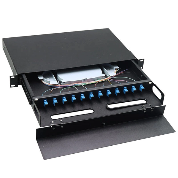
As an essential component of optical fiber communication, optical modules are optoelectronic devices that facilitate the conversion between optical and electrical signals during the transmission process. Operating at the physical layer of the OSI model, optical modules are core devices in optical. The optical module serves as a crucial component in optical fiber communication systems, operating at the physical layer, which is the lowest layer in the OSI model. Classification of Optical Module: Distinguished according to function, package form, transmission rate, wavelength. In the era of 5G, AI, and high-speed data centers, optical modules serve as the core bridge for converting electrical signals to optical signals (and vice versa), enabling fast, reliable data transmission across networks. They are used in fiber optic communication systems to transmit data over long distances with minimal loss and interference. These modules typically consist of a laser or LED transmitter, a.
[PDF]
The hot and cold aisles in the data center are part of an energy-efficient layout for server racksand other computing equipment. The goal of a hot/cold aisle configuration is to manage airflow in a way that c.
[PDF]

Buy Panduit LabelCore Fiber Optic Cable Identification System Self-Laminating Laser/Ink Jet Labels at SHI. See detailed specifications and benefit from expert support. Shop IT hardware and software products with SHI now!. Indoor & outdoor fiber cable high visibility markers, id labels, printers, warning signs & posts, cable id sleeves and more for fiber optic applications. Check each product page for other buying options. Need help? Explore write-on fiber optic cable tags with self-laminating protection. Keep your cables organized and clearly labeled with writable identification solutions. The Multilink cable markers utilize a simple and quick installation that allows the installer to simply wrap the marker around the selected cable without the need for special tools or adhesives. The UV stabilized body will not degrade in outside applications and a variety of colors allows easy. According to research conducted by industry experts that shows network failures cost businesses the equivalent of five thousand dollars per minute. If technicians aren't able to quickly recognize the correct cable, these minutes can add up quickly. The TIA/EIA-606-A standard has created a unified system that specifies a "common" method of labeling the complete telecommunication infrastructure. PANDUIT Labeling Software packages include all label formats for quick and.
[PDF]

Download the network server room closeup on fiber optic hub or switch for digital communications and internet in mainframe corporate business data center supercomputer. 11308806 royalty-free Stock Photo from Vecteezy for your project and explore over a million other images. 5,805 fiber optics room stock photos, vectors, and illustrations are available royalty-free for download. lan cable with fiber optic cable connected use for network product concept. A close-up. Search among 220 authentic server room network data center technology fiber optic cables internet infrastructure stock photos, high-definition images, and pictures, or look at other data center or server room stock images to enhance your presentation with the perfect visual. Ethernet cables and. Server room with switch, internet cables and wires. Fiber optic equipment in data center. Network background, panorama. Pro Photo Pro License What's This? Pro Content Why Pro? Free Download for Pro Subscribers! Download the network server room closeup on fiber. This resource was generated with AI. You can create your own using our AI Image Generator. These rules include PON architectures and new ways to install. North America has the biggest revenue share at 35%. Asia Pacific is growing very fast. Check what the building needs.
[PDF]
This comprehensive guide will delve into the best practices for cable removal, the benefits of maintaining a clean cable environment, and step-by-step instructions to ensure the process is efficient and compliant with industry standards. Every new installation means an increased number of low voltage cables that are cut and left in ceilings, floors, and walls. From a tenant or building owner's point of view, removing abandoned cable has. Effective cable removal ensures safety, optimizes performance, and prepares the infrastructure for future upgrades. Before beginning any installation, safety. Fiber-optic cables are the backbone of modern connectivity—powering 5G networks, global internet backbones, and data center interconnections with near-light-speed data transmission. While these cables are engineered for durability (with some rated to last 25+ years), they are not invulnerable. Even. Here are 5 vital rules for staying safe when you're working on fiber optic cables. Know the standards that apply to your work Whether you're installing new fiber optic cables or troubleshooting and repairing an existing fiber network, a working knowledge of the regulations that apply to your. In outside plant fiber optic installations, the biggest cause of network failure is likely to be electronic problems or, if it's in the cable plant, what is usually called “backhoe fade” for buried cables and “target practice” for aerial cables, both of which are self-explanatory.
[PDF]

It helps control and distribute electricity to different areas. Inside, you'll find parts like circuit breakers and fuses that protect the system from problems like overloads and short circuits. According to HSE fire and explosion guidance, fire protection installations must be suitably designed, accessible, and maintained to ensure effective operation during emergencies. Knowing the internal parts. Fire Pump Room Layout: Components and Description This document explains in detail the components of a fire pump room layout commonly found in building firefighting systems. The drawing includes tanks, pumps, valves, pipelines, and control systems, designed in accordance with NFPA 20 standards. ---. NFPA 70: National Electrical Code defines how power should be fed to fire pumps. This design guide is meant to provide code references and examples to help an electrical engineer determine basic criteria that must be met for the installation. What are the functions and uses of DB Boxes? What is a Distribution Box? A distribution box, or DB box, is a circuit breaker enclosure. The hub distributes electrical power from a single input source to various circuits throughout a. Electrical and Controls engineer, designed power systems and automation systems for water facilities in many states. I've implemented projects in 19 states over 30 years – with multiple individual projects exceeding $100M in construction I've designed projects for traditional design bid build.
[PDF]

This guide provides CISOs and IT leaders with an in-depth look at network security architectures. Perimeter security is the first line of defense, protecting the network from external threats. It includes firewalls, intrusion prevention systems (IPS), and other security devices that control network traffic at the network's boundary. When effectively designed, network security reduces threats like unauthorized access and malware from impacting your network or. Network security architecture is a strategy that provides formal processes to design robust and secure networks. Effective implementation improves data throughput, system reliability, and overall security for any organization. It explains the key concepts in plain language, dives into the core components, shares a framework for. Microsoft Defender for Cloud provides cloud security posture management (CSPM) and cloud workload protection (CWP). It assesses your resources for security compliance, provides a secure score to track your posture, and offers threat protection across Azure, on-premises, and multicloud workloads. It encompasses hardware, software, policies, and procedures.
[PDF]
Due to combinations of intense securitization, Western sanctions, foreign businesses exiting Russia, tech “brain drain,” and other factors, digital technological isolationism is now both a reality and a desired goal for Moscow. Digital technology has long been a key component of the Russian government's power, and for years following the collapse of the Soviet Union there was significant technology entanglement between Russia, the West, and other areas of the world. That changed in the late 2000s and early 2010s with. ANDREI SOLDATOV is a Nonresident Senior Fellow at the Center for European Policy Analysis and Co-Founder and Editor of Agentura. ru, a watchdog of the Russian secret services' activities. However, another set of players has a key role in the Russian cyber ecosystem: private sector. What's Next for Japanese Security Policy and U. -Japan Relations? Perspectives from the Diet The principal goals driving Russia's cyber strategy across the spectrum of conflict are clear: disruption, destruction, and control of information. Its cyber governance is centralised, hierarchi-cal and under the president's personal control. The country is highly dependent on foreign.
[PDF]

d Lighting Co Plc, here known as Kenya Power. This specification lays down requirements for Low Voltage (LV) Enclosures and Accessories for use in Advanced Metering Infrastructure (AMI) system. d Lighting Co Plc, here known as Kenya Power. Secpower Technologies LTD specializes in. Browse our comprehensive range of electrical products — from switchgear and panels to VFDs and smart components. ATS/MTS solutions from Paneltech Systems provide reliable Automatic and Manual Transfer Switches for seamless power transfer in industrial and commercial electrical systems. Distribution. th cable entry and termination of cables. Secure and Intelligent Spaces, Powered by HSC ELV Systems We deliver holistic Extra-Low Voltage (ELV) solutions that integrate Security, Fire and Automation into intelligent ecosystems. More than just equipment, our systems provide seamless control, uncompromising safety and optimised performance. Are you searching for a reliable Low Voltage (LV) Power Control Panel manufacturer in Kenya? We are Kenya's trusted source for custom-designed and precision-engineered power panels built for long-term performance and safety in industrial, commercial, and institutional setups. 🏭 Who We Are We are a.
[PDF]
Explore our broad line-up of equipment that generates hydrostatic servo driven pressure - pressure generated by compressing water in a still state. Your complete pumping solution for constant pressure, flow, booster systems, lift stations, and more. Choose from Enclosed Configured or Enclosed Bypass packages, available in UL Type 1, 12, or 3R cabinets, with essential pump features. This range includes equipment that is used in internal pressure fatigue tests of pressure vessels and piping. Sugino has been harnessing the power of. Any orders placed on or before March 31, 2024 will be honored. (excluding blanket orders) The type 350X is a direct replacement for all 3 types and features a significant increase in power and a more advanced brushless DC motor. The Servo team of engineers have created our most powerful and. The A-Series Servo Cylinder is a rod-style, brushless DC electromechanical actuator with built-in controller and Phase Index® absolute position sensor. Providing up to 530 lbf peak force and up to 7. 75” of travel, the Servo Cylinder was designed from the ground up to be extremely robust and very. integrally cast. Frame sizes 71 - 160 have pedestals t at are removable. Pressure die cast aluminum frame sizes re from 56 - 160. The SV3 Series servo system supports EtherCAT®, a globally popular Ethernet protocol. To enhance next-generation machine performance, the motor features a 26-bit encoder resolution and a.
[PDF]

When Batelco was first founded in 1981, Bahrain already had 45,627 telephone lines in use. By 1982, the number reached 50,000. Batelco enjoyed being a monopoly in the telecommunications sector for the next two. Telecommunications in Bahrain are provided by the Bahrain Telecommunications Company, trading as Batelco, as well as other companies such as Zain and STC. Prior to 1981 telecommunications services were provided by two separate departments: national services were provided by the Bahrain. Explore the evolution of BNET in Bahrain, a testament to the nation's commitment to advancing telecommunications infrastructure and connectivity. BNET won the Gigacity Excellence Award at the WBBA Broadband Excellence Awards 2024! Learn about BNET's evolution and its journey to provide advanced. alth, and to maintaining national competitive advantage. Change in information and telecommunications technology (ICT) has accelerated over the last two ecades, and these two areas have increasingly converged. Since then, other companies such as Zain and VIVA have entered the telecommunications sector. During the same year, Optical fibres and cables were the 479th most exported product (out of 3,333) in Bahrain. In 2024, the main destinations of.
[PDF]
WDM systems are divided into three different wavelength patterns: normal (WDM), coarse (CWDM) and dense (DWDM). Normal WDM (sometimes called BWDM) uses the two normal wavelengths 1310 and 1550 nm on one fiber. Coarse WDM provides up to 16 channels across multiple transmission windows of silica fibers. OverviewIn, wavelength-division multiplexing (WDM) is a technology which a number of signals onto a single by using different (i.e., colors) of. A WDM system uses a at the to join the several signals together and a at the to split them apart. With the right type of fiber, it is possible to have a device that does both s.
[PDF]