Flex electrical cable, often referred to as flexible cable or flex, is a type of wire that is designed to withstand repetitive bending and movement without damage. Article 400 covers the general requirements and applications for flexible cords as contained in Table 400. A “flexible cord” is two or more insulated conductors enclosed in a flexible covering. Figure 01 The NEC does not. What is a flexible cable? Flexible cables are cables that have multiple conductors (Class 5 or Class 6 conductors) that form the conductor and are insulated and sheathed in a lightweight, flexible material (usually plastic or rubber). Why choose flexible cables for domestic use? It is suitable for. These include flat flexible cable (FFC), stranded wire, power cables, control cables, and flexible electrical conduit. Each type meets specific needs across industries like automotive, electronics, and medical devices. Here is a quick look at how leading cable types are used worldwide: You can. Power distribution cables present a unique challenge to electrical wire interconnect system engineers. Unlike rigid electrical wiring, which is designed for static installations within buildings, walls, or. In any electrical system—whether powering lights in homes, machinery in factories, or robots in operation—cables are the unsung heroes, safely and reliably transmitting electrical energy. As the backbone of power distribution systems, cables connect power sources (such as circuit breakers) to.
[PDF]

Lighting Circuits: Use 1. 5 mm² copper wire. Dedicated Circuits: AC, geysers, and ovens should have 4. Main Incoming Cable: Use 10 mm² or 16 mm² for main supply connections. Also, consider. Professional electrical wire sizing tool based on National Electrical Code (NEC) standards. Calculate proper wire gauge, voltage drop, and ampacity for safe electrical installations. Input your electrical parameters to get accurate wire size. Comprehensive NEC-compliant electrical feeder size charts with copper and aluminum ampacity tables, voltage drop calculations, and real-world installation examples for safe electrical work. Electrical feeder sizing is one of the most critical calculations in any electrical installation, yet it's. This guide gives a clear tech look at home wiring sizes – breaking down what matters without fluff or filler. We'll show you clear, useful info and steps that make sense when setting up your setup. What is House Wiring Cable and Why Does It Matter So Much? Simply put, a house wiring cable is the. Choosing the right wire size is critical for electrical safety and code compliance. Whether you're building a new home, remodeling, or adding circuits, properly sized cables protect against overheating, voltage drop, and fire hazards. Incorrect sizing not.
[PDF]
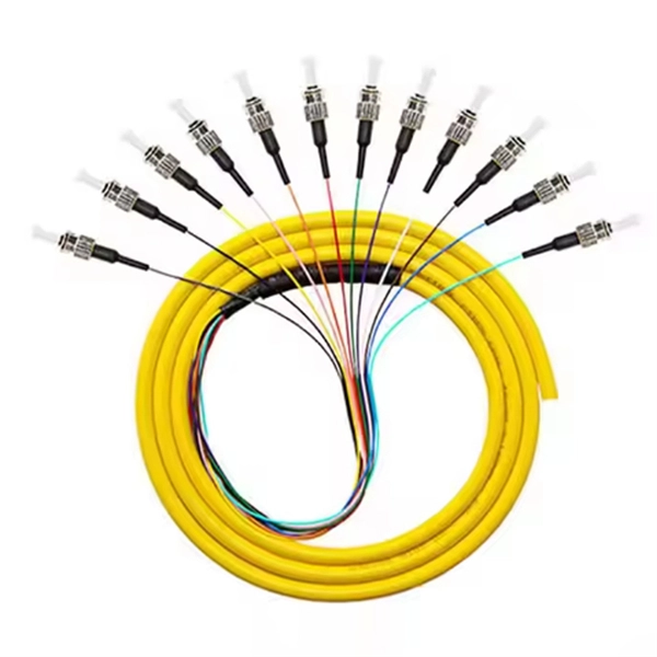
Huawei switches support optical modules of the following encapsulation types: CFP, QSFP+, QSFP28, XFP, SFP, eSFP, and SFP+. All optical modules are hot swappable. SFP: small form-factor pluggable. eSFP: enhanced small. Optical fiber active connectors: Optical patch cords, optical fiber connectors, optical fiber patch cords, Optical splitter: Optical fiber coupler, optical splitter, fused coupler, fused taper, planar waveguide optical splitter, plc splitter, coupler, blade type, box type, rack type, lgx, Fiber. Optical modules are important devices in fiber optic communication systems. and originated in Shenzhen. Huawei Technologies Co. is a telecommunications network solutions provider. Huawei's main business scope is switching. Optical modules are available in various types to meet diversified requirements. Depending on transmission rates, optical modules are classified into 100GE, 40GE, 25GE, 10GE, FE, and GE optical modules. 02315233 - Genuine Huawei SFP-FE-SX-MM1310 Optical Transceiver, SFP, 100M/155M, Multi-mode Module (1310nm, 2km, LC)Basic InformationModule name: SFP-FE-SX-MM1310Part Number: 02315233Model: SFP-FE-SX-MM1310Form factor: SFPApplication standard: 100BASE. Optical. The purchased products, services and features are stipulated by the contract made between Huawei and the customer. Unless otherwise specified in the contract, all.
[PDF]

The easiest way is to use the $3 "spec-grade" receptacles which come in a box instead of loose in a bin. If it's just black and white wires with a cloth or plastic covering and no ground wire you'd need a retroit grounding wire to have grounded outlets. A clearer picture of the cable entering will help. Can you post photos that show clearly where the cables enter the box at, please? @Traveler No!. The process of wiring a small breaker box, often called a subpanel, is a common task when adding power to a detached structure like a shed, garage, or a major home addition. These smaller distribution centers are designed to take power from a larger main service panel and distribute it locally to. How do I wire a mini circuit breaker distribution box that doesn't have bus bars? I have a circuit going to my shed from my house and I want to have two separate breakers inside the shed (one for outlets, one for other stuff) so I bought this from amazon (Amazon. com: 2 Way Distribution Box Circuit. In this video, we'll walk you through the process of wiring a home distribution box with a detailed connection diagram. more Welcome to our channel! In this video. Connecting a distribution box involves several steps to ensure proper electrical flow. But first, the rules: Turn off the power when working with electricity. Make sure the power's off using a non-contact voltage tester or multimeter. One final tip: Get into the habit of making connections in this.
[PDF]

Launched in 1995 by China Telecom, ChinaNet (AS 4134) or “163 net” is not only China's national internet backbone, it is also widely considered an important part of the global internet. ChinaNet boasts the most subscribers, websites, widest coverage and richest infrastructure resources of any. China Telecom's Global Internet Access offers enterprises access to ChinaNet (AS 4134) and CN2 (AS 4809) through a variety of bandwidth speeds and Internet access technologies. In addition, China Telecom offers you diversity of service level options and dedicated connections from over 110 markets. Follow China Telecom Global WeChat official account, chat live with us. From simple to enterprise-level solutions, we provide diversified ICT products with one-stop services. The ultra-low latency, high redundancy helps enterprises to operate at stable environment. Our global internet service offers premium China connectivity worldwide, customized route options, carrier-grade network security, and a variety of bandwidth speeds and Internet access. What is APN Settings for China Telecom? APN stands for Access Point Name. To access the internet via China Telecom SIM, you must configure APN Settings on your device. It is the name of a gateway between a GSM, GPRS, 2G, 3G, 4G, LTE, VoLTE, or 5G mobile network and another computer network. The. Checking your browser before accessing undefined. Click here if you are not automatically redirected after 5 seconds.
[PDF]
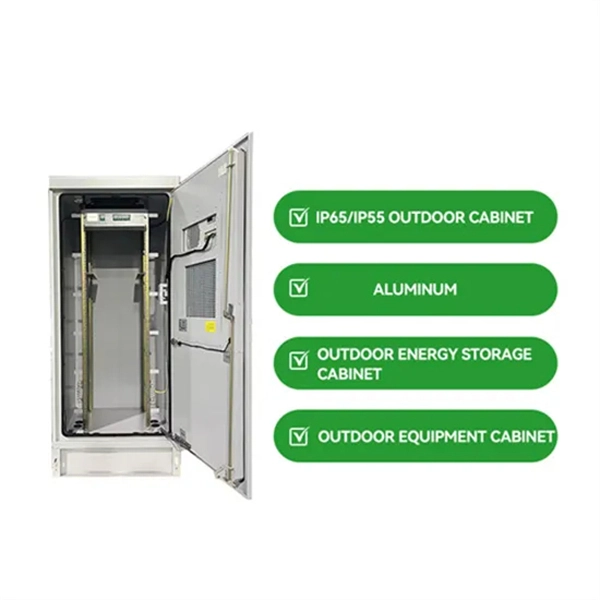
Voltage level: Industrial facilities often use multiple voltage levels (such as 1kV, 10kV, 400V), and it is necessary to ensure that the cable distribution box layout separates different voltage systems to avoid interference. A distribution box is the heart of any electrical system. It takes the incoming power and safely distributes it to different circuits throughout your building. Whether in a home or an industrial facility, this box keeps your electrical setup organized, functional, and efficient. However, the key to. Design requirements for low voltage distribution boxes cover NEC, IEC, and safety standards to ensure reliable, compliant electrical installations. You must make safety your top priority when working with low voltage distribution boxes. Protection requirement: According to the fault risk (such as short. For Branch Circuits (the conductors spanning from the final overcurrent device or breaker to the actual outlet, light fixture, or equipment), NEC Informational Note No. 4 recommends a maximum voltage drop of 3%. This ensures that the device at the end of the line receives at least 97% of the panel. For distribution boxes that handle only lighting circuits or small power loads, if the incoming wire size is less than 10 square millimeters and the number of circuit switches is fewer than 20, the width of the box should be calculated by summing the width of the switches and adding an additional.
[PDF]

It consists of an optical fiber and a lens, where the fiber guides the light and the lens collimates it. The primary purpose of a fiber collimator is to couple light efficiently from a fiber into free space or another optical component, ensuring minimal divergence and optimal. Fiber-optic collimators are used to launch the light from an optical fiber into a free space collimated beam with specified beam diameter or spot size. In essence, a simple collimation lens is all that is needed for this purpose. They are widely used in. To couple light both into and out of an optical fiber, it is essential to have a collimated light beam. To meet this demand, LASER COMPONENTS developed its own collimator systems. It typically consists of: Optical fiber section – single-mode fiber (SMF) is most common, but polarization-maintaining (PMF) or multimode fiber (MMF) can also be used. Miniature lens – such as a C-lens. Other fiber collimators have a mechanical interface to a fiber connector, e. of FC or SMA type; they are not for use with bare fibers. One can easily attach and remove such a collimator from a connectorized fiber. Commercially offered collimators may offer several directional adjustments, e. Our Polaris ® Kinematic Collimators offer high-quality.
[PDF]

Direct attach cable with auto link optimization for seamless 1G SFP, 10G SFP+, and 25G SFP28 interconnects between UniFi devices. What is an uplink port on a network switch? What is the difference between an uplink port and a normal port? How do you use an uplink port on a network switch? What are the various port types on a network switch? Which cable types can be used with an uplink port? Q: Why is the uplink port on a. For most missions the communication system enables the spacecraft to transmit data and telemetry to Earth, receive commands from Earth, and relay information from one spacecraft to another. A communications system consists of the ground segment: one or more ground stations located on Earth, and the. So, the uplink port connects the switch to other switches or “higher” layer routers. Additionally, the core-layer switch uplink port connects to the external network. Uplink ports are usually faster than normal ports to handle traffic from multiple devices. It essentially facilitates upward connectivity towards a more central or higher-level device in the network hierarchy. An SFP (Small Form-factor Pluggable) uplink port is a critical component in modern networking equipment, such as switches, routers, and other devices that facilitate data communication within a network.
[PDF]

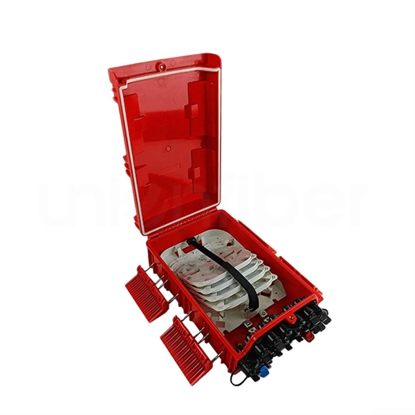
A Fiber optic cap type splice box is a protective enclosure designed to house and organize fiber optic splices. It typically features a dome or cap-style closure that provides a sealed environment for fiber joints, protecting them from external conditions. As fiber optic networks continue to expand across urban, rural, and industrial environments, the reliability of connection points becomes. The cap-type splice box is mainly designed for laying optical cables in overhead and tunnels. It does not meet the waterproof requirements of the regulations when used in direct-buried lines, but the moisture-proof effect in lines is better. According to regulations, the open type and other three. The types of optical cable splice boxes can be divided into cap-type optical cable joint boxes and horizontal optical cable joint boxes according to the shape and structure. According to. Grandway's fiber optic closure provides a high density wall mounted or pole mounted solution for next generation networks, which aims to provide and manage fiber splitters in a limited space. It is designed for FTTH (Fiber to the Home) or FTTB (Fiber to the Building) with protective housing for all. Briefly explain how fiber splice closures are critical for network protection and performance optimization. Introduce that choosing between dome (cap-style) and horizontal (in-line) closures depends on specific project requirements. Understanding Fiber Splice Closure Types 1.
[PDF]
The codes in Box 7 of your Form 1099-R indicate the type of distribution you received. DHCS created the Naloxone Distribution Project (NDP) to combat opioid overdose deaths through the provision of free naloxone. The NDP distributes both 4mg nasal naloxone and 0. 4mg/ml intramuscular naloxone, as well as fentanyl test strips. In 2024 the NDP began distributing generic 4mg naloxone. Our Christy range of concrete enclosures, lids and accessories provides robust, durable utility access in deliberate traffic environments and high-impact applications. With its AASHTO HS20 load rating, Christy enclosures are optimized for use on roadways that experience heavy vehicular traffic. Many people think distribution boards and distribution boxes are the same, but they're not. They may sound similar, but they have different roles in electrical systems. Knowing the difference helps you choose the right one for your needs. Several distribution boxes are designed for specific use in offices or industries. Enter the information from your 1099-R exactly as. A distribution boxes acts as the load center and main distributor of electrical power within a building. Also called a distribution board, panel board, breaker panel, or electric panel, it is the central hub in an electrical system that divides incoming power into various subsidiary circuits.
[PDF]
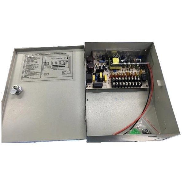
A distribution box is used to receive electrical power from a main supply and distribute it to multiple branch circuits in a safe and controlled way. It helps protect circuits, organize electrical connections, and improve maintenance efficiency. Distribution. Distribution boxes are commonly used in residential and commercial electrical systems. To learn more about distribution boxes and how they work, keep. A distribution box is a vital piece of equipment that ensures the effective and safe distribution of electrical power in various parts within a building or complex. Today, electrical systems are essential for homes and industries. It acts like a hub or traffic controller, managing power flow to different areas or devices. Key components include circuit breakers, fuses, bus bars, and internal wiring for safety and. This ultimate guide explains what a distribution box does, its internal components, common types, real-world applications, and how to select the right DB Box for your project. We also highlight how reliable manufacturers like NUOMAK support stable, compliant, and cost-effective power distribution.
[PDF]

Link Aggregation is a generic term for combining multiple network connections to work as one logical connection. It is standardized under the IEEE 802. So, what exactly is an aggregation switch, and how do you choose the right one? Let's examine it in detail. What Is an Aggregation Switch? An aggregation switch is a network device that consolidates traffic from multiple access switches, wireless access points, or other edge devices and forwards it. Is a Aggregation switch just to connect different networks? I have all my Clients wired into the USW Pro this is connected to the UDM by 10g fibre. The NVR is connect via Fibre to the USW as well. So. ? Any hints welcome! Archived post. New comments cannot be posted and votes cannot be cast. The primary function of an aggregation switch is to aggregate and forward data. Link Aggregation, Port Channel, and EtherChannel are related concepts in networking that involve combining multiple physical network links into a single logical link to increase bandwidth, redundancy, and fault tolerance. Let's break them down: 1. A round-robin algorithm is used for load balancing traffic across the interfaces in an aggregated link. Dynamic Link Aggregation (LACP) has been introduced on SonicOS 6. Link. LAG simplifies controller configuration by eliminating the need to configure ports for each interface. If any controller port fails, traffic migrates automatically to other functioning ports. Wireless clients.
[PDF]

Silicon, toughened glass, aluminum, and electrical metals are carefully chosen materials that are used to make panels that work well and last a long time. All of these parts work together to turn the sun's rays into electricity that can be used. They can be put on roofs or in. We look at the raw materials of a PV module including busbars, and junction boxes to the cell itself. A solar, or photovoltaic (PV) module as it is also called, is a device that converts sunlight into electricity. It is the key component of a solar energy system. Solar panels convert sunlight into. Most panels on the market are made of monocrystalline, polycrystalline, or thin film ("amorphous”) silicon. In this article, we'll explain how solar cells are made and what parts are required to manufacture a solar panel. Most homeowners save around $60,000 over 25 years Solar panels are usually. A solar panel is made of different raw materials like frames, glass, backsheets, and others. Each of the raw materials for solar panels plays an important role in generating electricity. Aluminum Alloy Frames Regarding solar. Discover the key materials that make up modern monocrystalline solar panels, what role each material plays, and where these materials usually come from. Sunlight first passes through a protective layer (usually glass) and then enters the solar cell through a. The cell to module process starts with very pure materials. They also affect how long the panels last.
[PDF]