No, a 10G SFP (Small Form-factor Pluggable) module is designed to operate at 10 Gigabits per second (Gbps) and is not compatible with a 1 Gigabit per second (Gb) port. Therefore, a 10G SFP module will not work. When SFP optical module is inserted into the SFP port of Gigabit switch with fiber optic patch cable or copper cable, it can realize different distance transmission. For example, the maximum transmission distance is 160 km when using SFP1G-ZXC-55 optical module and LC duplex fiber patch cable, and. 10 Gigabit Ethernet (10GE, 10GbE, or 10 GigE) is a group of computer networking technologies for transmitting Ethernet frames at a rate of 10 gigabits per second. It was first defined by the IEEE 802. For example, when using the AE-SFP-ZX160 optical module and LC duplex fiber optic patch cords, the maximum transmission. Can 1G SFP optics work with 10Gb SFP+ ports on a 10Gb switch, or vice versa? This comprehensive guide reveals the intricacies of SFP and SFP+ compatibility and provides useful solutions for network switch users. Can 1G SFP Optics Run at 10G SFP+ Port? Can 10G SFP+ Optics Run at 1G SFP Port? Can. Small form-factor pluggable or SFP Modules can be described as compact and hot-pluggable hardware that connects various networking devices such as servers, routers, and switches. Networking standards, including Ethernet, Fiber Channel, and SONET, are also used with the SFP modules, broadening their.
[PDF]
Dense wavelength-division multiplexing (DWDM) refers originally to optical signals multiplexed within the 1550 nm band so as to leverage the capabilities (and cost) of EDFAs, which are effective for wavelengths between approximately 1525–1565 nm (), or 1570–1610 nm (). EDFAs were originally developed to replace optical-electrical-optical (OEO), which they have made pra.
[PDF]
With 14 top 10G Ethernet switches for 2025, discover the best options to elevate your high-speed network—continue reading to find your ideal match. The global market for 10 Gigabit Switch was estimated to be worth US$ million in 2024 and is forecast to a readjusted size of US$ million by 2031 with a CAGR of %during the forecast period 2025-2031. A 10 Gigabit switch is a network switch that supports data transfer rates of up to 10 gigabits per. In this guide, we've tested and reviewed the best 10Gb switches to help you make an informed decision. From performance to features and value for money, we will walk you through everything you need to know to pick the ideal 10Gb switch for your needs. Check out the thorough review of the best 10Gb. Advantech's industrial Ethernet solutions provide an abundance of product options including managed and unmanaged switches, Gigabit Ethernet switches, PoE switches (IEEE 802. 3at), protocol switches, EN50155 and IEC61850-3-certified switches, and SFP modules with rackmount and. Moxa provides a wide range of industrial Ethernet switches that feature industrial-grade reliability, network redundancy, strengthened security, easy management, and competitive price-to-performance ratios. These 10G industrial switches deliver ultra-fast connectivity with support for 10Gbps data rates, ensuring seamless communication for bandwidth-intensive applications.
[PDF]

No, single-mode SFPs are designed to work with single-mode fiber cables and multimode SFPs are designed to work with multimode fiber cables. Attempting to use a single-mode SFP with a multimode fiber cable could result in poor network performance or data transmission errors. It utilizes ultra-low optical attenuation for medium to long transmission. The single mode SFP generally uses high-cost FP and DFB lasers with long wavelengths to optimize. Single-mode (SMF) and multi-mode fiber (MMF) use different core sizes, sources and wavelengths. Understanding the compatibility constraints prevents costly downtime and troubleshooting. To address this question, it's important to understand the characteristics of both single-mode and multimode fiber optics, as well as the implications. Multimode fiber (MMF) uses a larger core diameter (typically 50 or 62. 5 microns) allowing multiple light modes to propagate, suitable for short distances. In contrast, single mode fiber (SMF) has a smaller core diameter (~9 microns) supporting one mode of light, enabling longer reach with minimal. SFP modules are compact, hot-swappable devices used in networking equipment to facilitate the connection of fiber optic cables. They come in two primary types: single-mode and multimode. Single-mode SFPs are designed for long-distance communication, typically using a laser as the light source, and.
[PDF]

The following are the precautions for the use of Gigabit optical transceivers and 10 Gigabit optical transceivers, some common fault causes, and corresponding troubleshooting methods and solutions. Avoid damage. In the formation of modern networks, optical modules are essential equipment, of which Gigabit optical modules and 10 Gigabit optical modules are popular because of their high speed and stable transmission rate and wide applicability. However, the failure of optical modules is a common problem. 10G SFP+ optical modules remain one of the most widely deployed transceiver solutions in data centers, telecom networks, enterprise switching, and cloud-scale architectures. Their compact size, low power consumption, and versatility across multimode and single-mode fiber make them a critical. Gigabit optical transceivers and 10 Gigabit optical transceivers are an essential part of modern network communication, but they will inevitably encounter some failures during use. This article dives into technical specifications, real-world usage scenarios, selection criteria, and. Single-fiber bidirectional (BIDI) optical modules must be used in pairs. For example, SFP-10G-BXD1 must be used with SFP-10G-BXU1. Cisco XFP Module Main features of the Cisco XFP Module include:.
[PDF]

Click to get your 10G SFP+ transceiver modules from nearby warehouses. Trusted by 260K+ Enterprise Users. Discover the Brocade Compatible 10G SFP+ BiDi Transceiver with 1270nm TX / 1330nm RX, 10km reach, LC SMF, DOM, industrial grade for reliable high-speed networking. Compatible with 10G-SFPP-BXU-I. The LINK-PP LS-BL273310-10I SFP+ transceiver is fully compatible with Extreme 10GB-BX10-U-I. The. FS 10GbE SFP+ module solutions provide a wide variety of 10 Gigabit Ethernet connectivity options for data centers, enterprise wiring closets, Internet Service Providers (ISPs) applications. Trusted by 260K+. Find competitive sfp module prices for various optical transceivers. Our range includes 1. 25G, 10G, and 25G modules with different reach and compatibility. Fiber optic transceiver modules are fiber cable adaptive housings that contain a light source for transmitting data via fiber optic cable as well as a photodiode for receiving fiber optic data. Mounting options include pluggable CXP, QSFP, SFF, SFP, and XFP, surface or through-hole, CFP, 1x9 SC. 10G SFP+ transceivers are available in many different transmitting and receiving types. Users can select the appropriate transceiver for each link to provide the "optical performance" that can be achieved based on the fiber type available such as multi-mode or single-mode optical fiber. Moxa's small form-factor pluggable transceiver (SFP) Ethernet fiber modules for Fast Ethernet provide coverage across a.
[PDF]

10 Gigabit optical transceivers have higher speed and better performance than Gigabit optical transceivers. However, compared with Gigabit optical transceivers, the price of 10 Gigabit optical transceivers is also more expensive. While they function similarly, there are many differences in price. This. Gigabit optical modules have a wide range of applications in enterprise networks, data centers, and video transmission, and are seen as a solution that balances bandwidth and cost. Demand for gigabit optical modules still dominates the current networking market. It is widely used in various types. SFP+ modules support the following data rates: 1 Gbps. Many SFP+ modules are backward-compatible with SFP transceivers that support slower data rates. SFP+ modules are specified for. When shopping for optical modules, we need to compare different specifications of optical modules and choose the model that suits our application from to ensure that it is compatible with our equipment and meets our needs. In this article, we will conduct a comparative analysis of 10 Gigabit.
[PDF]

Fiber optic cable suspension clamp installation manual made by Jera line. Developed to provide a quick access to attach the fiber optic cable to the pole, using the suspension clamp HC-8-15, stainless steel band, buckles and strapping tool MBT-004. more. This guide will explain the entire set of activities involved in installing Fiber optic cable contractors -from the early planning stage right through testing-for facility managers, IT teams, and low-voltage contractors to build high-performance networks safely and efficiently. The processes. You simply can't handle and install fiber optic cable using the same methods that are used for copper. The relative fragility of fiber when compared to copper cable requires special care, special practices, and attention to detail during handling and installation. (FOA) was founded in 1995 to help develop the workforce to build the fiber optic networks to support a rapid expansion in communications and the Internet. The charter of the FOA was to promote professionalism in fiber optics through education, certification, and. The FIBERLIGN Suspension uses a combination of structural reinforcing rods (SRR), outer rods, housing halves, and resilient inserts to reduce compression, clamping, and bending stresses on OPGW and the optical fibers within it. SRR and outer rods cannot be reused. Different environments demand different fiber optic cable installation methods: aerial cables strung on poles.
[PDF]

Practice good wiring: secure grounding, neat cable management, proper insulation, and correct wire gauge and breaker size. Include protection devices like breakers, fuses, and surge protectors—each circuit should have its own protection. Comply with standards: Follow NEC, IEC . Learn how to wire a distribution box step by step! This video shows real on-site footage of electrical installation, demonstrating safe and standardized wiring methods used by professionals. It serves as a central hub for distributing electricity throughout a building, ensuring that power is delivered safely and efficiently to all the required locations. Hey, in this article we are going to see the Single Phase Distribution Box Wiring Diagram and Connection Procedure. Whether you're an electrician or a DIY enthusiast, this guide will help you understand the basics of home electrical distribution. What is Distribution Board? Distribution board. Material preparation: Prepare the required circuit breakers, wires, wiring ties and other materials, and ensure that they meet the design drawings and installation requirements. Location determination: Determine the installation position of the circuit breaker according to the position of the. A distribution box is the heart of any electrical system. It takes the incoming power and safely distributes it to different circuits throughout your building. However, the key to.
[PDF]

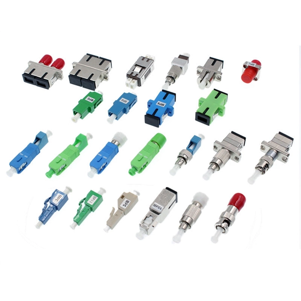
This video goes over common types of connectors, their respective adapters, and how to properly connect and disconnect them. more Are you interested in seeing how fiber optic connectors get. Unplugging a fiber jack, also known as a fiber optic connector, is a delicate process that requires attention to detail and proper handling to ensure the integrity of the fiber optic cables and connectors. Fiber optics are used in a variety of applications, including telecommunications, internet. If you're wondering how to remove fiber optic cable from connectors, there are a few different ways to do it. You need to know which connector is the correct one for the cable and what kind of wire it's made of. You can also use shears or wire cutters to cut through the connector. This article. Fiber optic connectors are essential components in fiber optic networks, providing a reliable connection between cables and equipment. Removing these connectors requires care to avoid damaging the delicate fibers or the connector itself. To connect a fiber optic cable to SFP optical module, first ensure the SFP is fully inserted into the network port until it "clicks", then remove the dust caps from both the SFP and the LC fiber optic connector.
[PDF]
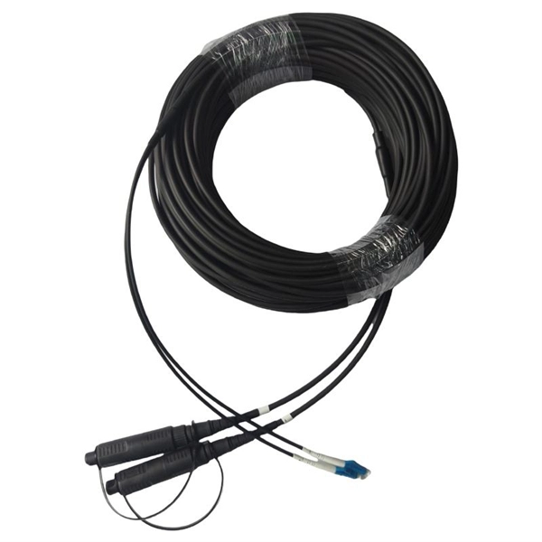
A single-mode fiber optic cable is an optical fiber designed to propagate light signals over long distances with minimal attenuation. It comprises one glass or plastic fiber and features a tiny core of about 8-10 microns in diameter. There are two main types of fiber optic cables: single mode and multimode. Although they can do the same job in some instances, the different construction methods make each of them better suited to certain tasks and budgets. That makes picking between single mode and multimode fiber optic cables an. Single mode fiber optic cable is made up of a small diameter glass or plastic core surrounded by cladding, which is a layer of reflective material. This small core permits only one light mode to propagate through. From the fiber core and core size to single mode fiber and multimode fiber cables, each type of optical cable serves a specific purpose depending on transmission distance, network requirements, and installation environment. In this guide, Omnitron Systems explores the key differences between. Unlike copper cables, which rely on electrical signals, fiber optics use pulses of light to transmit data—offering unmatched bandwidth, low interference, and long-distance capabilities. OS2 cable offers low signal attenuation and high bandwidth. For more detailed information, you can refer to the article Single Mode Fiber Wiki: Types and.
[PDF]
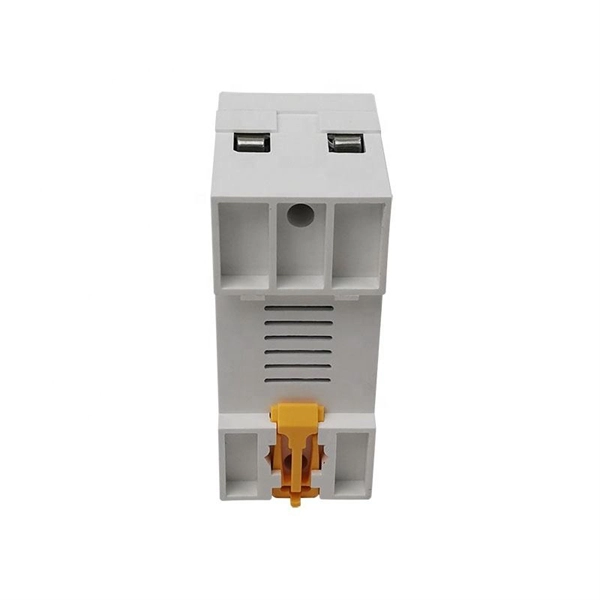
An electrical wire from the main power supply connects to the distribution box. Around this box, several circuits are attached. Each circuit has its own. Distribution boxes, also known as electrical distribution boards or panels, are pivotal components in electrical systems, ensuring the safe and organized distribution of electrical power throughout residential, commercial, and industrial environments. It receives power from the main electrical supply and divides it into separate circuits, each. Distribution boxes are an essential part of every home or building's electrical system. These enclosures house wiring connections for various applications such as switches, receptacles, and fixtures as well as transition wires for easy access. It takes the incoming power and safely distributes it to different circuits throughout your building. Whether in a home or an industrial facility, this box keeps your electrical setup organized, functional, and efficient. However, the key to.
[PDF]
Connect the input and output wires to the corresponding terminals of the distribution box. Then press the wire onto the terminal with a wire stripper, or tighten the wire with screws. This step is very crucial and can not bear any faults!. In this video, we'll walk you through the process of wiring a home distribution box with a detailed connection diagram. more Welcome to our channel! In this video. This guide provides step-by-step instructions for connecting a distribution box and highlights key factors to consider during installation. What Is a Distribution Box? A distribution box, also known as an electrical distribution board, is a critical component in electrical systems. It serves as a central hub for distributing electricity throughout a building, ensuring that power is delivered safely and efficiently to all the required locations. It is usually equipped with circuit breakers, fuses, terminal connectors, and other components.
[PDF]