This list was initially developed as part of AfTerFibre, a project to map terrestrial fibre optic cable projects in Africa. The project was sponsored by and, on completion, will be hosted by the UbuntuNet Alliance. All information gathered by the project will be publicly available under an open license.
[PDF]

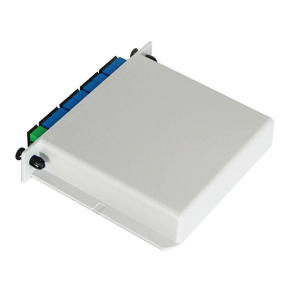
FTTH Networks: Wall-mount panels are used in apartment basements to distribute signals to individual units. Data Centers: High-density 4U panels are used for Top-of-Rack (ToR) switching. Broadcast & Media: Used for high-bandwidth 4K/8K video signal routing. This 2026 expert guide explains the functions, placement, structure, and application scenarios of ODFs and fiber patch panels-and includes a deep engineering FAQ that resolves real-world deployment challenges. Where Do ODF and Fiber Patch Panels Fit in a Modern Fiber Network? To understand the. Depending on different network construction scales and application environments, fiber optic cabinets and patch panels are typically used in various combinations. Choosing the right structural combination can significantly improve network construction efficiency. First is the standard. A Fiber Optic Patch Panel, also known as an Optical Distribution Frame (ODF) or fiber termination enclosure, is a centralized hardware unit designed to manage, protect, and organize fiber optic cable connections.
[PDF]
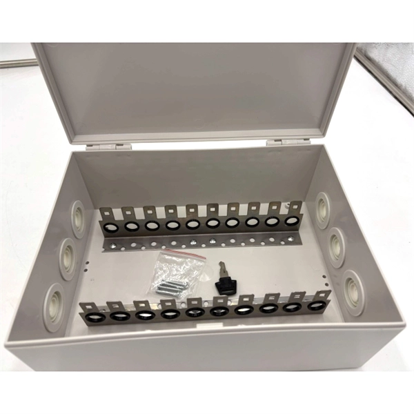
View inventory, pricing and order now for same day shipping!. View inventory, pricing and order now for same day shipping!. Check each product page for other buying options. This product has sustainability features recognized by trusted certifications. Learn more Need help? Find weatherproof electrical enclosures with stainless steel latches and hinged covers. Ideal. Polycase's IP67 rated enclosures and boxes provide protection for your electronics in indoor and outdoor applications. With a variety of sizes available in aluminum or. Box products are used to contain or enclose materials or equipment in a variety of contexts; plastic or metallic boxes suitable for constructing enclosures for electronic equipment such as guitar pedals, equipment cases for transporting tools or equipment, console style enclosures convenient for. An IP67-rated 19-inch metal enclosure rack is a high-performance housing solution designed to protect sensitive electronic and industrial equipment from dust, water immersion (up to 1 meter for 30 minutes), and harsh environmental conditions. They are perfect for use in a variety of applications, including industrial and commercial settings. Made from high-quality materials, these water-resistant enclosures offer a. Discover IP67 storage solutions with waterproof boxes and containers. Durable plastic, stackable design, and latching features for secure storage. Perfect for outdoor and rugged environments.
[PDF]

One rack unit equals 1. 45 mm), defined by the EIA-310. Measure your deepest server and add 3–6 inches for cabling and airflow. While rack height is standardized in rack units (U), external dimensions vary by manufacturer. A rack space calculator is a specialized tool designed to help data center professionals, IT administrators, and network engineers determine the optimal placement and space requirements for equipment in server racks. This calculator helps you plan rack layouts by calculating the total rack units. Server rack height is measured in rack units (U). Use the. When planning LAN infrastructure, selecting the correct data rack size is essential for proper equipment fit, ventilation, cable management, and future expansion. A practical formula often used for estimating the required rack size is: Rack size = 1. Common sizes: 42U, 48U, and compact options like 22U–27U. Standard width is 19 inches (EIA-310 compliant), while outer widths vary (e. Rack depth matters for. The three primary dimensions to consider are rack height (measured in rack units or U), rack width (most commonly the industry-standard 19-inch format), and rack depth (typically ranging from 24 inches to 48 inches). Each of these factors influences equipment fit, airflow management, cable routing.
[PDF]

This complete guide explores everything you need to know about ODFs — from their structure, types, and key components, to installation best practices and modern design trends. Achieve successful cable management, handle high amounts of fiber cable and add density to fiber frames with the new DCX Optical Distribution Frame (ODF) System which features innovations like flippable cassettes, modular frame design and multiple configuration options. The ODF System Components. What is an ODF Module? An ODF (Optical Distribution Frame) module is a specialized configuration where fiber optic cables are terminated, organized, and connected to network devices when necessary. Whether you're building a central office, data center, or FTTx distribution network, understanding the right ODF. 3U MGX Modular Patch Panel is a 288 LC high density fibre Splice and Patch unit. 19" rail ODF design with a splice & patch system for fibre cable management. Developed for high density applications on carrier & transmission side. Comprising of 12 MGX modules, 24 fibre count each. Designed to make.
[PDF]

See this topic to learn how to remove and install a door. Unlock and open the door. Removing a door Hold the door in place, and lift both hinge pins until they lock in the open position so that the door is disengaged. Remove the door from the rack cabinet frame. Install. Before installing your server in a rack cabinet, review the following guidelines: Two or more people are required to install the device in a rack cabinet. Ensure that the room air temperature is below 35°C (95°F). Do not block any air vents; usually 15 cm (6 in. ) of space provides proper airflow. In this comprehensive guide, we will walk you through the step-by-step process to ensure a successful installation and setup of your network cabinet system. Key steps include measuring the installation area, mounting rails, organizing cables, and testing stability. Proper grounding and compliance with safety. Page 3 M3. Click Side Panels (E) into place. To install the Tempered Glass Door (G), locate the side with two pins. With your thumb, pull down on the spring pin and slide it. Complete Assembly Procedure for 9U Wall Mounted Network Cabinet (Double Section) How to assemble a double section wall mounted network cabinet server rack? 1, Insert top and bottom panels into the side frames. And fixed the frame on the front door position with 4 M5*8 self-tapping screws.
[PDF]

The SS64S16A (L-16. 2,SC) is a Huawei high-performance STM-16 optical interface board designed to deliver 2. 5 Gbps long-haul transmission across SDH transport networks. The SFP-FE-SX-MM1310 (part number: 02315233) is a Huawei-certified 100M optical module. However, the Vendor Name field displays the original manufacturer name, instead of HUAWEI. Huawei. Optical modules are widely used in switches, network interface cards (NICs), routers, and other communication devices. During use, reading optical module information helps understand its real-time operating status, enabling faster troubleshooting of link abnormalities. The following uses the. Original SFP Huawei GPON-OLT-CLASS-C+/C++ Optical Module GPON Optical Module A GPON optical module is connected to one SC optical fiber to provide GPON access service. Return Material Authorization (RMA) Process Standard Hardware Warranty Policy: Original new sealed ZTE product: 1 Year The Support. Problem: All optical ports cannot be connected, and the indicator lights are not on. Solution: To solve this problem, you can follow these steps: Check if the fiber and optical modules are compatible. Perform a. Huawei GPON boards include GPON, XG-PON, XGS-PON, XG-PON&GPON Combo, XGS-PON&GPON Combo interface board, so there are these kinds of GPON optical modules corresponding. The following figure shows the optical modules supported by the S5720-12TP-LI-AC. You can also use the Hardware Center to query the.
[PDF]
An optical module is a typically hot-pluggable optical transceiver used in high-bandwidth data communications applications. Optical modules typically have an electrical interface on the side that connects to the inside of the system and an optical interface on the side that connects to the outside world through a fiber optic cable. The form factor and electrical interface are often specified by an int. Electrical Interface TypesThere have been multiple variants of the electrical interface of optical modules that have been used over the years. The earliest forms of optical modules had an analog electrical interface. In the transmit dir. Many different forms of optical modulation and multiplexing have been employed in optical modules. The most common modulation technique historically has been or NRZ.
[PDF]

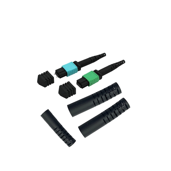
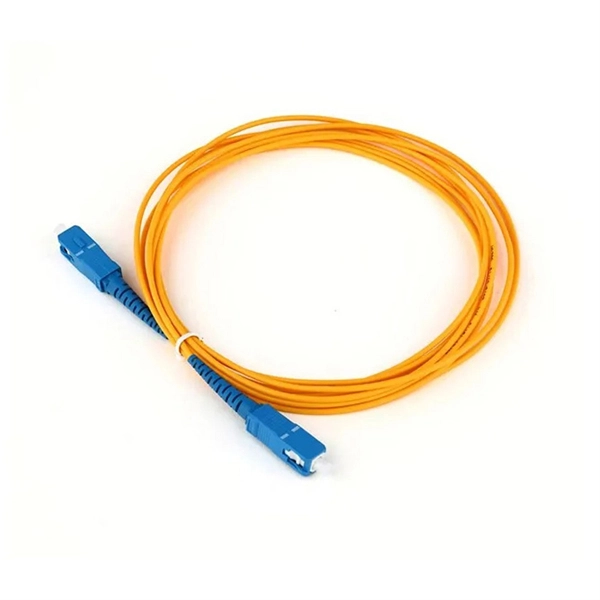
The FC/PC (Physical Contact) and FC/APC (Angled Physical Contact) fiber optic connectors are standardized under TIA EIA/TIA-604-4 and IEC 61754-13. ABSTRACT: This standard describes the point-to-point physical interface portions of Fibre Channel serial electrical and optical link variants that support the higher level Fibre Channel protocols includ-ing FC-FS, HIPPI, IPI, SCSI and others. This standard is recommended for new implementations but. Fiber connector types LC, SC, FC, ST, MTP, and MPO are widely used in past and present. What are the differences between them? Who is the most popular one? Find the answer in the article. What is a Fiber Connector? The optical fiber connector is a kind of detachable passive optical component used. An optical fiber connector is a device used to link optical fibers, facilitating the efficient transmission of light signals. An optical fiber connector enables quicker connection and disconnection than splicing. Unlike fiber splicing, which is permanent, connectors allow for easy connection and disconnection of cables, making them ideal for maintenance and flexibility in. Understanding fiber connector types—SC/APC, SC/PC, LC/UPC, LC/APC, ST/PC, FC/PC, and FC/APC—is essential for selecting the right interface for your application. Each type varies by shape, polish (APC, PC, or UPC), and return loss performance, which affect PC, UPC, and APC Polish Styles: What's the.
[PDF]
Compatibility in your network is everything, and the Intellinet SFP Transceiver Module delivers. Use it with any Intellinet SFP equipped network switch or any other MSA-compliant, SFP-enabled switch. And.
[PDF]

Of the more than a dozen types of fibre-optic connectors available, the four most commonly used today are LC, SC, FC, and ST. Fiber connector types LC, SC, FC, ST, MTP, and MPO are widely used in past and present. What are the differences between them? Who is the most popular one? Find the answer in the article. What is a Fiber Connector? The optical fiber connector is a kind of detachable passive optical component used. Fiber optic connectors are the unsung heroes of modern networking. They are small, often overlooked components, yet they are essential for ensuring high-speed, low-loss, and reliable optical transmission. In addition to serving the same general function, the four connectors differ in size, locking mechanism, and best applications. The following guide systematically describes. Choosing the right connector for an optical link is one of those small decisions that has outsized effects on installation density, reliability, and long-term maintenance. broadband connection is available everywhere. Its. Optical fiber terminations are the mechanical and optical interfaces that connect fiber cables to equipment, patch panels, and network hardware. They directly affect insertion loss, return loss, reliability, and long-term network stability. In this guide, we break down the most common optical fiber.
[PDF]

The interface fc command displays the Fibre Channel (FC) interface view. Specifies the number of an FC interface. Devices on a storage area network (SAN) use FC interfaces to communicate and carry traffic. You can then perform. FC switches are required for applying for DESS devices of the common I/O (low latency), high I/O (low latency), or ultra-high I/O (low latency) types. An FC switch is a high-speed network transfer device that uses optical fibers as the media. It features high-speed transfer and strong. Get the latest official Huawei FC - Application Interface port (COM/LPT/Serial) drivers for Windows 11, 10, 8. Update drivers using the largest database. The good news is that HF now shows two ports in the COM dropdown and is recognized in Mobile Partner! The bad news is that reading still fails, no matter what port combo I specify, even modem port. These are the observations before/after setting AT^SFM=1. Thus we lost SD card as a recognized drive. Copyright © 1998-2026 Huawei Device Co. FCF functions as the access switch and connects the storage device Array through its uplink interfaces, and directly connects to ServerA through its downlink interface, as shown in Figure 2-35. ServerA connects to FCFA and FCFB to constitute dual-plane networking, ensuring network reliability.
[PDF]
FC used throughout all applications for Fibre Channel infrastructure and devices, including edge and ISL interconnects. Each speed maintains backward compatibility at least two previous generations (I.e., 32GFC backward compatible to 16GFC and 8GFC)OverviewFibre Channel (FC) is a high-speed data transfer protocol providing in-order, lossless delivery of raw block data. Fibre Channel is primarily used to connect to in (SAN) in co. When the technology was originally devised, it ran over optical fiber cables only and, as such, was called "Fiber Channel". Later, the ability to run over copper cabling was added to the specification. In order to avoid confu.
[PDF]