
It's called a breaker box, and even though it might not look very exciting on the outside, what's behind that little door is the heart of your home's electrical system. Bottom Line Up Front: Your home's distribution box (electrical panel) is typically located in the basement, garage, utility room, or mounted outside near your electrical meter. To find it quickly, look for a rectangular gray metal box about the size of a medicine cabinet, often positioned close to. Electrical panel boxes, aka breaker boxes, can be on a wall in an out-of-the-way area of your home. You can find electric panels inside cabinets, behind refrigerators, or inside clothes closets in older homes. Current National Electrical Codes (NEC) allow none of these locations. Electrical panels. The electrical panel is the central hub that distributes electricity throughout the house. Knowing where to find your electrical panel in your home helps in case of emergencies and routine maintenance. Panels are commonly found in garages, basements, utility rooms, and outdoor walls. Understanding how your electrical panel works can help you troubleshoot issues, perform basic maintenance, and know when to. When something electrical goes wrong in your home—like a tripped circuit or sudden power outage in one part of the house—most people instinctively head to that gray metal panel, often hidden in a basement, utility closet, or garage. Having the breaker box.
[PDF]

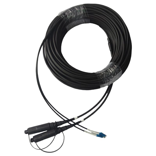
Every fiber optic patch cable has a rated attenuation and bandwidth. For example, OM1 is rated at 200 MHz·km at 850 nm and is intended for use in legacy applications. The higher OM ratings provide more speed and distance. Attenuation should remain within acceptable limits for reliable transmission. Executive Summary: Choosing the right fiber patch cable is one of the most consequential decisions in network infrastructure planning. The wrong choice — whether it's an underperforming multimode grade or an unnecessarily expensive singlemode run — can either cripple your network's reliability or. Fiber optic patch cords are key components for efficient, low-loss optical signal transmission between devices and fiber optic cabling links. One or both ends of the patch cord are equipped with standardized fiber optic connectors, and common interfaces include LC, SC, FC, ST, etc. They are manufactured and tested in compliance with TIA 604 (FOCIS), IEC 61754 and YD/T industry standards. OM1, OM2, OM3, OM4, OM5 or OS2 fiber types are available to meet the demand of. Fiber optic patch cables are ideal for supporting high speed telecommunication network fiber applications. They are lengths of optical fiber terminated with connectors on both ends. Their job is to connect two optical devices, like switches, routers, or optical transceivers that communicate.
[PDF]

Mainly 9steps: Step 1: cut cable with cutting machines in lengths Step 2: put the connector spare parts on the cable Step 3: Strip cable jacket, coating till bare fiber, and make all parts in ready Step 4: Insert fiber into ferrule, glue dispenser and heat oven Step 5:. Mainly 9steps: Step 1: cut cable with cutting machines in lengths Step 2: put the connector spare parts on the cable Step 3: Strip cable jacket, coating till bare fiber, and make all parts in ready Step 4: Insert fiber into ferrule, glue dispenser and heat oven Step 5:. Learn how to make a fiber optic patch cord step by step, from preparation to testing, for reliable high-performance connections. Most guides on making fiber optic patch cord 1 s feel incomplete. They often focus on the final assembly steps, leaving the foundational stages a mystery. From cable cutting to connector assembly and testing, you will gain valuable insights into the production of. Fiber optic patch cords and Pigtails are very important passive fiber optic components in fiber optic networks. Use the fiber optic cleaver to cut the. This document describes the installation and use of the mode-conditioning patch cords listed in Table 1. A mode-conditioning patch cord is shown in Figure 1 IEEE 802. 3z-compliant optical fiber assembly consisting of a single-mode fiber permanently coupled off-center to a 62. 5-micron multimode.
[PDF]

This comprehensive guide will walk you through the entire process of making fiber optic patch cords. From cable cutting to connector assembly and testing, you will gain valuable insights into the production of these essential components in telecommunications and data transmission. Producing high-quality fiber optic patch cords involves precise steps and procedures. You will. Optical fiber patch cords are critical components in fiber optic communication systems. They are used to connect different devices, such as routers, switches, and servers, in the network. They often focus on the final assembly steps, leaving the foundational stages a mystery. Prepare Tools and Consumables: Automatic Cable Cutting Machine, Scissors, Tape Measure, Cable Ties, Tape 1)First check the optical cable according to the requirements on order; then measure the length LCM. An optical fiber patch cord is a critical component used in fiber optic networks to connect different devices for signal transmission. These patch cords are factory-terminated and tested to ensure high performance and low signal loss. However, with the right equipment and technical know-how, they.
[PDF]

In this video, we'll walk you through the process of wiring a home distribution box with a detailed connection diagram. This guide provides step-by-step instructions for connecting a distribution box and highlights key factors to consider during installation. What Is a Distribution Box? A distribution box, also known as an electrical distribution board, is a critical component in electrical systems. Whether you're an electrician or a DIY enthusiast, this guide will help you understand the basics of home electrical distribution. It serves as a central hub for distributing electricity throughout a building, ensuring that power is delivered safely and efficiently to all the required locations. It is usually equipped with circuit breakers, fuses, terminal connectors, and other components. It is mainly used to isolate fault circuits, prevent overload, and ensure the safe operation of. The steps to install a small distribution box include selecting a suitable location, installing the base, placing the distribution box, connecting the wires, and checking for acceptance. Warm reminder: Do not disassemble or modify without experience and professionals. Select location Before.
[PDF]

Fiber optic cable suspension clamp installation manual made by Jera line. Developed to provide a quick access to attach the fiber optic cable to the pole, using the suspension clamp HC-8-15, stainless steel band, buckles and strapping tool MBT-004. more. This guide will explain the entire set of activities involved in installing Fiber optic cable contractors -from the early planning stage right through testing-for facility managers, IT teams, and low-voltage contractors to build high-performance networks safely and efficiently. The processes. You simply can't handle and install fiber optic cable using the same methods that are used for copper. The relative fragility of fiber when compared to copper cable requires special care, special practices, and attention to detail during handling and installation. (FOA) was founded in 1995 to help develop the workforce to build the fiber optic networks to support a rapid expansion in communications and the Internet. The charter of the FOA was to promote professionalism in fiber optics through education, certification, and. The FIBERLIGN Suspension uses a combination of structural reinforcing rods (SRR), outer rods, housing halves, and resilient inserts to reduce compression, clamping, and bending stresses on OPGW and the optical fibers within it. SRR and outer rods cannot be reused. Different environments demand different fiber optic cable installation methods: aerial cables strung on poles.
[PDF]

Testing solar panels is easy with a multimeter! To test the current, simply connect the multimeter to the panel's output. Set it to read DC current. To test voltage, set your multimeter to. A $15 multimeter and 5 minutes of testing can diagnose most solar panel problems. Measure Voc (open circuit voltage) — if it reads 0V, the panel or wiring is dead. If it reads 60–80 % of rated, a bypass diode has failed. If Voc is normal but the system is not producing, the problem is downstream. Solar panels are usually tested under standard conditions using a light source that mimics the light from the sun on a clear day. You can use the following method if you want to test your solar panel under standard conditions. We will cover the. A multimeter is a tool that measures the voltage, current, and resistance of an electrical circuit. Fluke recommends using the Fluke 117 Electrician's Multimeter or Fluke 283 FC CAT III 1500 V Digital Multimeter to test solar modules. This helps you spot issues early and keep your system running efficiently. By the end of this guide, you will be equipped with the knowledge to diagnose.
[PDF]

They are manufactured and tested in compliance with TIA 604 (FOCIS), IEC 61754 and YD/T industry standards. OM1, OM2, OM3, OM4, OM5 or OS2 fiber types are available to meet the demand of Gigabit Ethernet, 10 Gigabit Ethernet and high speed Fiber Channel. Fiber optic patch cords, also known as fiber optic patch cables or fiber jumpers, are indispensable components in modern optical networks. They act as the critical link for interconnecting devices like optical switches, servers, and distribution frames. Understanding the various technical. Designed for data center, enterprise, FTTx, LAN and WAN, CATV network, telecom network applications, etc. Fiber optic patch cables are ideal for supporting high speed telecommunication network fiber. Fiber optic patch cords are essential components in modern optical communication networks, widely deployed in data centers, telecommunications, FTTx systems, and enterprise cabling infrastructures., which can be. As networks move to higher speeds and higher density, choosing the right fiber optic patch cords becomes critical to the reliability of your system. At ZION Communication, we design and manufacture a full range of fiber patch cords for: This guide will help you quickly understand the main types of. Our fiber optic patch cords are factory terminated, inspected and tested to meet industry standards. They are available in either riser or plenum flame rating, and have a 2. 0mm thick color-coded jacket.
[PDF]

Connecting a fiber patch cord involves carefully inserting it into the appropriate adapter after ensuring the connectors are clean. The process may differ slightly depending on the type of connector. The core process involves two main stages: preparation and insertion. Planning helps you pick the right cord for your network. Be gentle when you handle the cord. Fibre patch cords last longer and are tougher than copper cables. They also protect better from interference. Look at the table below to compare:. Connecting a fiber optic patch panel may seem daunting at first, but if you follow the right steps, it's actually quite simple – and can even be done in just a few minutes. Preparation: Before. Fiber Optic Transceivers: For converting signals between optical and electrical form. Cleaver: For precisely cutting the fibers. Safety Equipment: Gloves. In today's high-performance networks, fiber optic patch cables are the lifelines that ensure smooth data flow across switches, servers, and routers. Even the most advanced optical transceivers can only perform at their peak when paired with properly installed, clean, and precisely managed fiber. Correct patch-cord installation is essential for maintaining low insertion loss, stable return loss, and long-term reliability in both indoor and outdoor fiber networks. Proper handling, routing, cleaning, bend-radius management, and connector alignment ensure that the optical link meets design.
[PDF]
In a modern data center, every high-speed optical link depends on the right fiber patch cable. These short fiber optic cords connect transceivers, switches, patch panels, and servers. Without them, even the best optical modules and switches cannot deliver performance. The fiber optic patch cable must, therefore, be carefully considered. Behind its slender appearance lies the fusion of core types, connector types, and polish levels, each chosen for a specific application. This guide will cover fiber optic patch cables, including their components, applications. When you build or upgrade a fiber network, the same four words pop up everywhere— fiber optic (bare fiber), pigtail, patch cord, optical cable. They're related, but they are not interchangeable. Mixing them up drives costs higher, increases loss, and slows your rollout. The good news? Once you nail. Unlike traditional copper cables, fiber optic patch cords utilize light to transmit information, making them an ideal choice for high-bandwidth applications and long-distance communication. In this blog, we will delve into what a fiber optic patch cord is, how it operates, and the significant ways.
[PDF]
A single-mode fiber optic cable is an optical fiber designed to propagate light signals over long distances with minimal attenuation. It comprises one glass or plastic fiber and features a tiny core of about 8-10 microns in diameter. There are two main types of fiber optic cables: single mode and multimode. Although they can do the same job in some instances, the different construction methods make each of them better suited to certain tasks and budgets. That makes picking between single mode and multimode fiber optic cables an. Single mode fiber optic cable is made up of a small diameter glass or plastic core surrounded by cladding, which is a layer of reflective material. This small core permits only one light mode to propagate through. From the fiber core and core size to single mode fiber and multimode fiber cables, each type of optical cable serves a specific purpose depending on transmission distance, network requirements, and installation environment. In this guide, Omnitron Systems explores the key differences between. Unlike copper cables, which rely on electrical signals, fiber optics use pulses of light to transmit data—offering unmatched bandwidth, low interference, and long-distance capabilities. OS2 cable offers low signal attenuation and high bandwidth. For more detailed information, you can refer to the article Single Mode Fiber Wiki: Types and.
[PDF]

The main service panel is typically located in a home's basement or utility room. Some homes also have a subpanel—a smaller version of the main panel—to control electrical circuits in a garage, workshop, or other outbuilding. The National Electrical Code (NEC) does not specify a minimum height for an electrical panel, although practical access for service should always be considered. But there is a maximum height allowed for an electrical panel, which is based on the height of the highest breaker switch in the panel. NEC Article 408 covers switchboards, switchgear, and Panelboards installation and applications. Guidelines set by the National Electrical Code (NEC) provide a framework that ensures these installations adhere to stringent safety protocols. This article provides an exhaustive examination of the principles and standards governing the height at which electrical panels should be installed. The National Electric Code (NEC) includes the minimum standards for installing a circuit breaker panel box. These standards set the minimum safety standards for panel boxes. Tomorrow I'll be looking at a panel that was installed in a dining room knee wall 18" above floor. You can find electric panels inside cabinets, behind refrigerators, or inside clothes closets in older homes. Electrical panels.
[PDF]

The use of locking cabinets with advanced steel and tamper-resistant designs utilizes physical barriers to limit access to sensitive materials, making them harder to reach for unauthorized individuals. This pressure can cause the gap below server cabinets, which is often 2” or more, to become an air stream between hot and cold aisles. The resulting mix of air reduces the effectiveness of a containment solution. The Cool Shield Magnetic Cabinet Skirt provides an easy fix for this issue. These. Commercial environments have evolved as technology advances, and having a robust cabling infrastructure is crucial for scalability, minimising downtime, and enhancing productivity. Educational institutions are increasingly adopting smart technologies and cloud-based resources, so the foundation of. Many network devices are stored in the cabinets. In order to meet the normal operation of these devices in the cabinets, when the computer room cabinets are full of various cabinets and devices, we need to consider how to place the network cabinets? 1. Network cabinet placement skills (1) Before. A network cabinet is defined as a physically enclosed compartment built to store networking gadgets like patch panels, modems, switches, and a multitude of cables. Network cabinets support large, modular network switches by providing additional space for cable management and side-to-side airflow solutions. Networking cabinets tend to have.
[PDF]