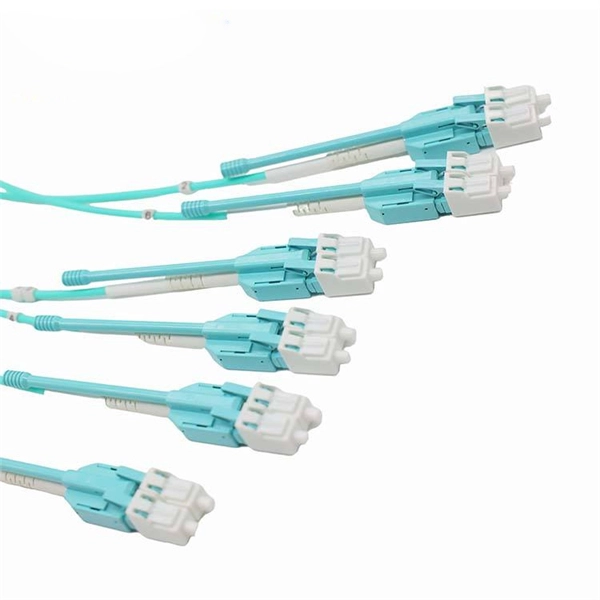
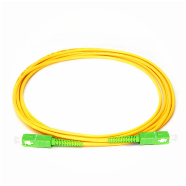
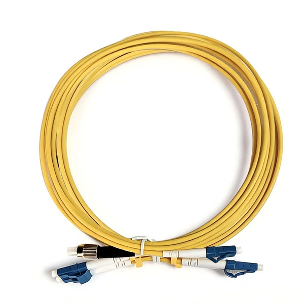
This guide explains fiber optic cable construction, the difference between tight buffer and loose tube structures, and compares eight common cable types used in data centers, enterprise networks, and FTTH deployments. The Fiber Optic Association, Inc. (FOA) was founded in 1995 to help develop the workforce to build the fiber optic networks to support a rapid expansion in communications and the Internet. The charter of the FOA was to promote professionalism in fiber optics through education, certification, and. 40. FO-VC2 JOINT USE - VERICAL MIDSPAN CLEARANCES 48. FO-GB GROUNDING AND BONDING 49. APPENDIX A - COVER SHEET / TOC 52. Building a fiber optic network is a highly technical yet vital process that enables communities and businesses to access high-speed, reliable fiber optic internet. From the initial site survey to the final fiber to the home (FTTH) connection, every stage requires careful planning, coordination, and. Fiber optic cables facilitate high-speed connectivity with significant advantages over copper wires, such as faster data transmission, greater bandwidth, and better security; single-mode fibers are ideal for long distances, while multi-mode fibers suit short-range communications. Proper fiber optic. Fiber optic cables come in many designs depending on where and how they are deployed. The method covers the steps from receiving the materials on the installation site and cable pulling as per the approved shop drawings.
[PDF]
Because fiber optic cables don't come in one continuous length, sections must be joined together through splicing. This process fuses two glass strands so light signals can travel through them without interruption. Below is a detailed look at each step of fiber optic network construction, including key terms and methods used across the industry. Engineers and. We are experts in the installation and use of fiber optic cable to residences, apartment buildings, businesses and cell sites. We complete complex construction projects consisting of aerial and underground deployments in varied, often difficult, working environments. Our services include everything. The Fiber Optic Association, Inc. (FOA) was founded in 1995 to help develop the workforce to build the fiber optic networks to support a rapid expansion in communications and the Internet. Delivers state-of-the-art fiber optics solutions by developing high-tech equipment and subcontractor expertise. Utilizes state-of-the-art technologies to splice a wide variety of different. This recommended practices document is a comprehensive manual for optical fiber construction and testing. Sections are included for project management; cable handling, testing and equipment; overhead cable placement; underground cable placement; underground enclosures; bonding and grounding; cable. 4. FO-VC2 JOINT USE - VERICAL MIDSPAN CLEARANCES 48. FO-GB GROUNDING AND BONDING 49.
[PDF]
Discover AZE's advanced All-in-One Energy Storage Cabinet and BESS Cabinets – modular, scalable, and safe energy storage solutions. Featuring lithium-ion batteries, integrated thermal management, and smart BMS technology, these cabinets are perfect for grid-tied, off-grid, and. rgy storage technology has become a key pillar in building new-generation power systems. It is being widely deployed across grid peak-shaving, me retardancy, non-toxicity, RoHS/R foam, addressing the dual needs of noise and thermal control in energy storage systems. This solution has been. Relying on its cutting-edge clean power conversion technology, industry-leading battery technologyand grid forming technology, Sungrow focuses on integrated energy storage systemsolutions. The core components of these systems include PCS, lithium-ion batteries and energy management systems. But hold onto your solar panels, because this Middle Eastern gem is quietly becoming a laboratory for energy storage innovation. From government officials sweating over. Energy experts have lauded the Cabinet's recent approval of a grid-scale battery energy storage system (BESS) for the National Electric Power Company's transmission. Hybrid Solar-Geothermal Heat Pump Systems: Simulated for various Jordanian locations, these systems incorporate storage to optimize.
[PDF]
The World Bank Group has approved plans to develop Botswana"s first utility-scale battery energy storage system (BESS) with 50MW output and 200MWh storage capacity. The World Bank will support the 4-hour duration BESS via a loan of US$88 million. Botswana has today marked a historic milestone in its energy transformation journey with the groundbreaking ceremony and signing of the Power Purchase Agreement (PPA) for the 500MW Maun Solar Photovoltaic (PV) Plant and 500MWh Battery Energy Storage System (BESS), one of the most ambitious. By 2030, 140MW of BESS will be needed to support the uptake of renewable energy generation. This financial boost will fund the construction of a 100-megawatt solar power plant and support a comprehensive renewable energy program designed to bring. Botswana has received an $88 million loan from the World Bank for its first utility-scale battery energy storage system (BESS). The 50 MW/200 MWh project will allow for the stable integration and management of renewable energy on the nation"s grid. In conclusion, the strategic imperatives. The World Bank has provided Botswana, one of the world's fastest-growing economies, with a loan to finance a 50 MW/200 MWh battery energy storage system, the nation's biggest such project to date.
[PDF]
Energy Internet integrates small-scale renewable energy systems, electric loads, storage devices, and electric vehicles for effective transaction of power backed by emerging technologies such as Internet of Things, vehicle-to-grid, and blockchain. Energy Internet, a futuristic evolution of electricity system, is conceptualized as an energy sharing network. Its features, such as plug-and-play mechanism, real-time bidirectional flow of energy, information, and money can lead to significant benefits and innovation in electricity production and. Future Electricity System Based on Energy Internet: Energy storage system.
[PDF]
The Aggregation Switch has a 160 Gb/s switching capacity with a 119. 04 Mpps forwarding rate, features steel construction with a fanless design, and can be rack mounted using the included kit. An Aggregation or "Top-of-Rack" switch is designed to connect everything in a rack at high speeds, then have an even bigger pipe out to the rest of the network. Power Consumption A 32-port, Layer 3 switch made for high-capacity 10G SFP+ and 25G SFP28 connections. The three layers of a traditional three-layer network design are the core layer, aggregation layer, and access layer. As the physical part of the aggregation layer, aggregation switches typically play a. IEEE 802. 3ad link aggregation enables you to group Ethernet interfaces to form a single link layer interface, also known as a link aggregation group (LAG) or bundle. The LAG balances. What is an Aggregate Switch? Understanding Centralized Network Management An aggregate switch is a high-capacity network switch that consolidates connections from multiple access switches, acting as a central point for managing network traffic and providing enhanced bandwidth capabilities. It is. Switch aggregation, also known as link aggregation or trunking, is a method used in computer networking to combine (aggregate) multiple network connections in parallel. This arrangement increases throughput beyond what a single relationship could sustain, offers redundancy in case one of the links.
[PDF]

The formula used to calculate cable tray capacity is: Cable Tray Capacity = (Tray Width × Tray Depth × Fill Ratio) / Cable Cross-sectional Area Where: Tray Width is the internal width of the cable tray in meters (or millimeters). Using our advanced cable tray load calculator is simple and ensures your electrical installation meets structural and safety standards. Follow these steps to generate your accurate Bill of Materials (BOM) and engineering report: Step 1: Define System Specifications: Select your cable tray type. Wire Mesh Cable Tray Fill Ratio = Cross section of cable / Cross section of tray According to NEC 392. 9 (B), when using ventilated tray with multi conductor control cable, the sum of the cross sectional areas shall not exceed 50 percent of the interior cross section of the cable raceway / tray. We independently provide precision steel tools, calculators, and expert resources for steel, metalworking, construction, and industrial projects. I'm here to tell you, it's simpler than you might think, and it makes a huge difference. This guide will walk you through how to work out those loads. An overloaded cable tray can lead to structural failure, causing damage to cables and potentially resulting in costly downtime and safety hazards. Divide this by the cross-sectional area of a single cable to find the.
[PDF]

This video shows real on-site footage of electrical installation, demonstrating safe and standardized wiring methods used by professionals. more Learn how to wire a distribution box step by step!. Temporary power systems are essential for construction projects, yet they often introduce serious safety risks. Loose wiring, exposed connectors, and unstable electrical connections can cause shocks, equipment failures, or costly downtime. This article examines how modern portable power cabinet. work requires electrical power for many purposes. However, exposure to weather, frequent relocation, rough use and other condi-tions not normally encountered with conventional wiring systems necessitate special consideration not require in other applications or in completed structures. The. Metal raceways, cable armor, and other metal enclosures for conductors shall be metallically joined together into a continuous electric conductor and shall be so connected to all boxes, fittings, and cabinets as to provide effective electrical continuity. The requirements of Article 590 apply to temporary power and lighting installations and removals, including. Learn what OSHA requires for temporary wiring on construction sites, from grounding and GFCI protection to overhead clearances and employer liability. Temporary wiring on construction sites must comply with the electrical safety standards in 29 CFR 1926, Subpart K. These federal rules, enforced by.
[PDF]

Fiber optic construction is a rapidly growing field in the United States, driven by the increasing demand for high-speed internet and data transmission. This guide provides a comprehensive overview of the process, from planning and permitting to installation and testing. Ervin Cable Construction, LLC (“ECC”) delivers quality turnkey services to multiple cable, energy, and communications companies. At Ervin Cable Construction, we are continuously expanding our capabilities within the industry. ECC has been operated by the same family since its humble beginnings in. The Fiber Optic Association, Inc. (FOA) was founded in 1995 to help develop the workforce to build the fiber optic networks to support a rapid expansion in communications and the Internet. The charter of the FOA was to promote professionalism in fiber optics through education, certification, and. Fiber Technologies Solutions, LLC ("Fiber Tech") provides a wide range of services to both telecommunications and cable providers across the U. FiberTechs is a full-service fiber optics telecommunications contracting company. It is designed to help. FO-CS JOINT USE CLIMBING SPACE REQUIREMENTS 51. APPENDIX A - COVER SHEET / TOC 52. RUS DRAWING #PM12 58.
[PDF]

The purpose of the present invention is to provide an explosion-proof and flame-retardant distribution box, which has good explosion-proof and flame-retardant effect, strong impact resistance, is not easy to disperse, and has reliable safety performance. Flameproof enclosure (Ex d IIB+H2), which can be used as feed distribution equipment in control and distribution system (such as distribution box, switch box of main circuit, control box, terminal box or motor starting box etc. ) ·Enclosure: stainless steel. Equipped with specialized hinge. Substructure (use SSS=) and similarity (use ~) searches are limited to one per search at the top-level AND condition. Exact searches can be used multiple times throughout the search query. Searching by SMILES or InChi key requires no special syntax. To search by SMARTS, use SMARTS=. To search for. REV. Durable Hexlon Explosion Proof Distribution Boxes and Electrical Enclosures, IECEx and ATEX certified for Zone 1 and Zone 2. Design explosion-proof distribution box (control box) to meet equipment category and group requirements; b. They include fully modular low- and medium-voltage Ex-e, Ex-d, and Ex-p solution components, from Switchgear, Splitter Boxes, Junction Boxes, Ring Main Units, Power Supply, Motor.
[PDF]

DFM in optical design refers to the process of designing optical components and systems that are manufacturable, testable, and inspectable. The importance of DFM lies in its ability to reduce production costs, improve product quality, and accelerate time-to-market. The SPIE Digital Library's coverage of design for manufacturability (DFM) predominantly centers on semiconductor and optical system manufacturing. The content heavily emphasizes photolithography-related DFM, detailing techniques for optimizing mask designs, optical proximity correction, and. Design for manufacturability (DFM) is a critical first step in the development of any optical component. In the context of optics, DFM involves optimizing the design of optical components and systems to minimize production costs, reduce. Optical assembly manufacturing combines precision components such as lenses, prisms, mirrors, and other components that must perform in demanding environments. Taking complex optical systems from simulation into production involves meeting a range of mechanical, functional, and other requirements. Today, we are expanding my very first blogpost from 2020 and discussing the concept of Design for Manufacturability (DFM). In this article, we explore why DFM matters and how key design aspects influence the success of plastic optics. Understand the Limitations of Injection Molding.
[PDF]
In this paper, we present this new method of building OMS-OOCCN or its model. System design Our method applies three key information processing techniques such as geographic information system (GIS), simulation and expert system (ES) ones. We developed a specialized Geographic Information System for an internet service provider operating a fiber-optic network across multiple neighboring locations. Really, they are also the most important techniques for. Location Data (C. Summary of descriptive data (C. Manage Fiber Optics Network (maintenance &operation) (C. Final. A leading telecom infrastructure provider responsible for planning, deploying, and maintaining optical fibre cable (OFC) networks to expand digital connectivity across urban and rural regions. The client needed a reliable and accurate system to document, monitor, and manage thousands of kilometers.
[PDF]

Relay protection is the discipline of designing schemes that detect faults, coordinate relays, and isolate equipment without outages. It emphasizes selectivity, coordination, fault response, and system behavior rather than individual relay devices. Relay protection is often misunderstood as a. A protective relay is an intelligent electrical device designed to detect faults in power systems and initiate corrective actions such as tripping a circuit breaker. : 4 The first protective relays were electromagnetic. This document provides recommendations, background and philosophy on relay protection that is not available in M07. The facilities to which this Document applies are generally comprised of the fol-lowing: In analyzing the relaying practices to meet the broad objectives set forth, consideration must. What is a Protective Relay? A protective relay is an intelligent device that senses abnormal electrical conditions, such as overcurrent, under-voltage, or frequency deviations. It initiates the operation of circuit breakers to isolate the affected section. This prevents damage to equipment, reduces. Protective relays and devices have been developed over 100 years ago to provide “lastline”of defense for the electrical systems. They are intended to quickly identify a fault and isolate it so the balance of the system continue to run under normal conditions. The selection and applications of.
[PDF]