This article provides a detailed technical comparison between fiber optic and copper cables, offering a clear perspective for engineers, network architects, and procurement managers. The core distinction between the two technologies lies in the physics of data. However, the exponential growth in data demand has positioned fiber optic technology as the superior alternative for performance, scalability, and future-readiness., 10G/25G/40G/100G and beyond depending on optics and reach). Copper Ethernet scales too, but practical limits are lower and depend. The two main options are fiber optic cables and copper cables, each with its own advantages and drawbacks. Fiber optic cables are praised for their high performance and scalability, while copper cables remain a cost-effective choice, especially for budget-conscious projects and older systems. Copper wire is more susceptible to interference and has limited data capacity, making optical fiber the preferred choice for modern high-speed. Optical connectivity, utilizing fiber-optic technology, has emerged as the superior choice for modern networking, offering unparalleled performance, reliability, and scalability. For example, a typical 10 Gbps copper Ethernet link (such as Cat 6A) over 100 meters can consume approximately 5 to 8+.
[PDF]

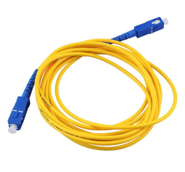
Compare fiber optic and copper Ethernet cables across speed, distance, cost, installation difficulty, and use case metrics. Use the interactive scenario selector to find the right medium for your specific network — all processed locally in your browser. PoE Required?. The core difference between fiber optic and copper cables lies in how they carry data. One uses light, the other electricity—and that distinction shapes everything from speed to signal integrity. Fiber optics transmit data as pulses of light through ultra-thin strands of glass or silica. Both technologies can deliver high-speed connectivity, but they behave differently under real-world constraints such as. However, the exponential growth in data demand has positioned fiber optic technology as the superior alternative for performance, scalability, and future-readiness. This article provides a detailed technical comparison between fiber optic and copper cables, offering a clear perspective for. Fiber optic tends to be the more premium solution, while copper wiring is far more common, but why is that? What are the differences between these two cable types, and why might you want to pick one over the other? Here's everything you need to know about fiber vs. copper cables, to help you pick. Several factors are converging to drive the switch from copper to fiber – and cost is a big one. A recent investor presentation by AT&T claimed that fiber was 35% less costly to maintain than copper.
[PDF]

This guide covers planning, installing, managing, and maintaining fiber optic cabling systems according to industry standards like TIA-942, BICSI, and FOA guidelines. You'll learn how to: Disorganized cabling creates direct financial consequences. Cable management involves organizing and securing network cables in a data center to ensure efficient operation and maintenance. It also facilitates easy. Data center performance and reliability fundamentally depend on proper fiber optic cable management, especially as bandwidth demands and density increase. According to the Uptime Institute's 2024 Annual Outage Analysis, over 54% of significant data center outages cost more than $100,000, with 16%. Effective data center cable management isn't just about aesthetics—it's about maximizing efficiency, ensuring reliable operation, and supporting future growth. With data volumes increasing in modern data centers, the complexity and density of cabling infrastructure continue to grow. Data center cable management includes methods, procedures and products to keep the cabling infrastructure in a neat and proper condition during the full data center lifecycle. With multiple tenants and varying connectivity needs, optimizing cabling strategies is essential. With data centers' growth in size and complexity, a holistic approach toward cable organizations would significantly cut down service restoration and improve cooling and maintenance.
[PDF]
The standard specifies the geometrical, mechanical, and transmission attributes of a single-mode optical fibre as well as its cable. The fibre has zero-dispersion wavelength around 1310 nm as per how it was designed, however it can also be used in the 1550 nm wavelength region. OverviewG.652 is an. G.652 was originally developed in 1984 by ITU-T Study Group XV. Subsequently, revisions were published in 1988, 1993, 1997, 2000, 2003, 2005, 2009, 2016, and 2024 (from 1997 as Study Group 15).
[PDF]

Under the TIA/EIA-598-C standard, the universal 12-color sequence is: 1-Blue, 2-Orange, 3-Green, 4-Brown, 5-Slate (Gray), 6-White, 7-Red, 8-Black, 9-Yellow, 10-Violet, 11-Rose, and 12-Aqua. This sequence repeats for cables with more than 12 fibers. Table 151-13 uses the worst case S0 and ZDW given in Table 151-14, and calculates the worst case positive and negative dispersion using the worst case TX wavelengths given in Table 151-7 and footnote (b), and the worst case fiber length (operating distance). 3 has analyzed. The two fiber parameters that have the greatest effect in limiting digital transmission over optical waveguides are attenuation and pulse spreading. In single-mode fibers, pulse spreading is caused by chromatic dispersion. Attenuation attracted most of the attention in the early years of. *Values for cabled fibre, local attenuation discontinuity ≤0. 1dBNote: Due to OTDR measurement uncertainty B3 International cannot guarantee attenuation values at fibres shorter than 1000m. Parameters are subject to change without notice. General Symmetric cable pairs Land coaxial cable pairs Submarine cables Free space optical systems G. 649 Optical fibre cables G. @1310nm (typical/max. The tutorial has the following parts: Chromatic dispersion is the phenomenon that the phase velocity and the group velocity of light propagating in a fiber depend on the optical frequency. It is relevant for many applications.
[PDF]

A well-built fiber link rarely fails, but when it does the symptoms can be short, confusing, and expensive to chase. This guide lists the actual, field-proven problems technicians encounter most often and gives step-by-step troubleshooting actions you can copy into your maintenance routine. Keep. Fiber optic troubleshooting is an essential skill for network administrators, technicians, and engineers responsible for maintaining and repairing fiber optic systems. These high-speed, high-capacity communication networks are increasingly replacing copper cables, offering superior performance and. Ever wondered why your blazing-fast fiber optic internet suddenly slows to a crawl, or why your network connection drops out just when you need it most? You're not alone. Fiber optic cables are the backbone of modern industry and communication, but even the most advanced networks can run into. Fiber optic cables are the backbone of today's high-speed communication networks, powering everything from FTTH broadband to data centers. However, like any technology, fiber optic systems can encounter issues that affect performance. Understanding the common causes and solutions helps maintain. Even small forms of damage—from a bent cable to a rodent bite—can disrupt signals, cause costly outages, and require expensive repairs. This article outlines seven common issues that require professional fiber optic services.
[PDF]

Buy Panduit LabelCore Fiber Optic Cable Identification System Self-Laminating Laser/Ink Jet Labels at SHI. See detailed specifications and benefit from expert support. Shop IT hardware and software products with SHI now!. Indoor & outdoor fiber cable high visibility markers, id labels, printers, warning signs & posts, cable id sleeves and more for fiber optic applications. Check each product page for other buying options. Need help? Explore write-on fiber optic cable tags with self-laminating protection. Keep your cables organized and clearly labeled with writable identification solutions. The Multilink cable markers utilize a simple and quick installation that allows the installer to simply wrap the marker around the selected cable without the need for special tools or adhesives. The UV stabilized body will not degrade in outside applications and a variety of colors allows easy. According to research conducted by industry experts that shows network failures cost businesses the equivalent of five thousand dollars per minute. If technicians aren't able to quickly recognize the correct cable, these minutes can add up quickly. The TIA/EIA-606-A standard has created a unified system that specifies a "common" method of labeling the complete telecommunication infrastructure. PANDUIT Labeling Software packages include all label formats for quick and.
[PDF]
Directory of 84 fiber optic cable manufacturers in the US. Find fiber optic cable assemblies, connectivity products, and subsea cables, plus contact info and. Buyers seek manufacturers to solve challenges like achieving specific optical return loss (ORL) targets for. Thomas has been North America's number one industrial sourcing platform for more than 125 years. You can filter these companies by location, certifications, and more factors to easily find and connect with the right. 171 Fiber Optic Cable manufacturers listed. Fiber optic cable is composed of two layers of glass, the core, which carries the actual light signal, and the cladding, which is a layer of a glass surrounding the core. Narrow down on the. Find 1,029 Fiber Optic Cables suppliers with GlobalSpec. Our catalog includes 106,451 manufacturers, 20,792 distributors and 94,628 service providers. Charlton Precision. The data fields provide comprehensive information including a description of the Fiber Optical Cable product, its HSN code, shipment date, price, quantity, countries of origin and destination, ports of origin/destination, details of Suppliers and Buyers, and top decision makers' contact.
[PDF]

When it comes to testing fiber optic cables, a Visual Fault Locator (VFL) is an essential tool in your toolkit. A VFL is used to detect faults, breaks, or bends in fiber optic cables by emitting a bright red light that is visible even through the fiber's jacket. It's a cost-effective and. A Visual Fault Locator which can be also called visual fault identifier (VFI), fiber fault locator, fiber fault detector, etc., is a visible red laser light designed to inject visible red light energy into an optical fiber. Using a VFL to diagnose issues can save time and cost when diagnosing an. A visual fault locator is a compact, handheld device that emits a visible light beam, typically in the red wavelength range, through a fiber optic cable. It works by injecting a visible red laser light into the fiber, which can be seen through the jacket or at the end of the cable. If the light doesn't come out the other side, there might be a problem. You. And in the end we will show you how to use an old cell phone's camera to detect light in a fiber optic system. It uses a bright incandescent bulb or visible LED source to.
[PDF]

Download the most popular free Fiber optic cable card vectors from Freepik. Explore AI-generated vectors and stock vectors, and take your projects to the next level with high-quality assets!. Fiber U is the free online learning website of the FOA - the Fiber Optic Association, the international professional association and certifying body devoted to the development of a skilled workforce in fiber optics and telecommunication. Here you will find free online self-study courses, tutorials. Free online self-study programs on many fiber optics and cabling topics are available free at Fiber U, FOA's online web-based training website. FOA Reference Books (Available Printed or eBooks) The fiber book is available in Spanish and French as well as English. Click on any of the books to learn. Copyright © 2010- 2026 Freepik Company S. Dura-Line Academy and Broadband Nation are offering free training on fiber basics. Sign up for free here and gain access to all three 10-minute mini courses: Fiber-Optics 101: Learn the basics about fiber-optics theory, along with the different types of fiber and cables. FOA is also an internationally recognized certifying body for fiber optics.
[PDF]
dari hasil carian. Bid on readily available Malaysia Optical Fibre Cables Tenders with GlobalTenders, the biggest and best online tendering platform, since 2002. TendersOnTime, the most comprehensive database for Government Tenders and International Tenders; collects information on. Existing suppliers must register via the link in invitation email from TM Supplier Registration Unit. New suppliers need to register at https://tm. my/business-with-tm/registration. For login issues, visit https://supplier. com/ (click HELP button). Other inquiries: srm@tm. my Stay up to. Tender for Supply, Delivery, Installation, Testing and Authorization of One (1) Unit Arthroscopy Camera System and Small Joint Instrument with Instruments in the Orthopedic Department, Hospital Pasir Gudang,. Fresh and verified Tenders from Malaysia. Find, search and filter Tenders/Call for. Malaysia's public sector generates billions in contracts annually across these key sectors: Malaysia Tenders follow Malaysia procurement directives and are published through platforms like TED (Tenders Electronic Daily / OJEU). Businesses worldwide can participate in these high-value government.
[PDF]
The fiber connector types, sometimes referred to as terminations, link fiber optic cables together through terminals, switches, adapters, and patch panels, by bridging the gap between their internal glass fi.
[PDF]

Read on to learn how a systematic approach can streamline the process, mitigate risks, and elevate overall performance in telecommunications carriers. Fiber optic cables form the backbone of modern data transmission in telecommunications. Cable identification stands as a critical practice in fiber optic networks. Misidentification can cause downtime, disrupt essential services, and create safety hazards in data centers. Industry standards like TIA-606-B guide professionals to use color codes, print legends, connector types, and. Fiber Optic Cable Tags are the perfect choice for marking your ground level and underground cables. Custom Fiber Optic Tags available upon request. Sold in package of 50 (nylon ties sold separately). Online shipping rates and pricing may differ. Indoor & outdoor fiber cable high visibility markers, id labels, printers, warning signs & posts, cable id sleeves and more for fiber optic applications. Need help? Explore write-on fiber optic cable tags with self-laminating protection. Keep your cables organized and clearly labeled with writable identification solutions. Cable Tags (Cable ID Tags, Fiber ID Tags) simplify wire and cable identification! Cable Tags (Cable ID Tags, Fiber ID Tags) simplify wire and cable identification! Fiber Tag Generic (No Company name) 4 Inches long fits 1/2" to 1" line. They are responsible for carrying vast amounts of.
[PDF]