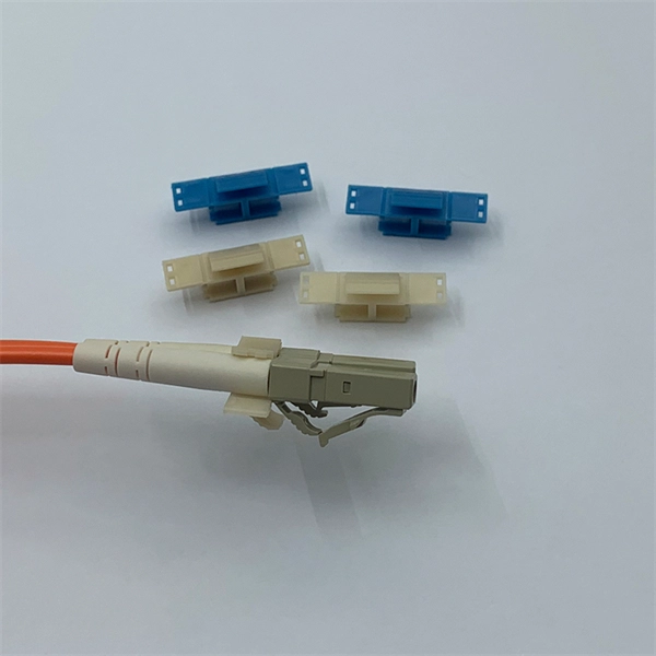
How to Install a Fibre Connector into a Patch Panel (Easy fibre optic connector installation) How to Install a Fibre Connector into a Fibre Optic Patch Panel. How do you install fibre optic connectors?. Connecting a fiber patch panel to a switch is a critical step in setting up a fiber optic network. There are different types of connectors. In today's high-performance networks, fiber optic patch cables are the lifelines that ensure smooth data flow across switches, servers, and routers. Even the most advanced optical transceivers can only perform at their peak when paired with properly installed, clean, and precisely managed fiber. Choose an SFP module based on the fiber optic cabling that will be connected to the network switches. SFP transceiver modules almost always require two fiber optic cable strands. A Fiber Patch cord connects two devices. You plug it into a switch, router, or patch panel. It's ready to use out of the box. A pigtail is for splicing. You fuse it to a. With a railroad switch (patch panel), the train (data) can travel from A to B, C and even more destinations, otherwise it can only go from A to B, or C to D. This article, What Is a Patch Panel Used for?, has explained it thoroughly.
[PDF]
24 Core GYTC8S Fiber Optic Cable Armor Stranded Loose Tube Steel Wire Strength Waterproof Figure 8 Self Supporting Outdoor GYTC8S cable, single-mode/multimode fibers are positioned in the loose tubes, which are made of high modulus plastic, while the loose tubes strand together around. 24 Core GYTC8S Fiber Optic Cable Armor Stranded Loose Tube Steel Wire Strength Waterproof Figure 8 Self Supporting Outdoor GYTC8S cable, single-mode/multimode fibers are positioned in the loose tubes, which are made of high modulus plastic, while the loose tubes strand together around. Corning ALTOS® figure-8 gel-free cables are self-supporting aerial cables designed for easy and economical one-step installation. The loose tube design provides stable performance over a wide temperature range and is compatible with any telecommunications-grade optical fiber. The gel-free design is. 24 Core GYTC8S Fiber Optic Cable Armor Stranded Loose Tube Steel Wire Strength Waterproof Figure 8 Self Supporting Outdoor GYTC8S is a typical self supporting outdoor fiber optic cable, suitable for aerial applications; The cable have nice moisture resistance performance and crush resistance. The fibers, 250µm, are positioned in a loose tube made of a high modulus plastic. The tubes are filled with a water-resistant filling compound. A steel wire locates in the center of core as a metallic strength member.
[PDF]
A 24-port patch panel is a networking device that allows for the organization and management of incoming and outgoing network connections. It acts as an interface between different devices such as computers, switches, and routers, allowing for easy connectivity and communication. This guide explains how to use a 24-port patch panel to manage copper and fiber cabling in a small LAN, how to choose between different patch panel types, how to design your cabinet layout, and why a patch panel is still irreplaceable in 2026. What is a Patch Panel and Why it Matters in 2026? A. Choosing a 24-port patch panel is crucial for efficiency. Learn how it enhances network capabilities. Typically, patch panels are available in a huge number of port densities from 12. In this article, we will define what a patch panel 24 port is, explain its purpose, and discuss why it is a crucial component in organising network cables. A patch panel 24 port is a device used in network cabling to connect and organise multiple network cables in one central location. It is a. Choose a 24-port patch panel when you care about clean labeling, comfortable “finger room,” and fast moves/adds/changes—especially if technicians touch the rack often and you want straightforward port-to-port mapping (Panel 01–24 ↔ Switch 01–24). Choose based on port density, cabinet space.
[PDF]

Run a ground wire from your metal patch panel rack to the grounding bar, use grounding lugs on the rack. Probably not necessary, but use Noalox between the lug and the rack. Remove paint if you want to go all in. Install and ground coax grounding blocks for your antenna. A Cat6 shielded patch panel is a modular component that connects and organizes multiple Ethernet cables in a central location. Unlike unshielded panels, shielded patch panels feature a conductive metal body and a grounding terminal to block EMI and maintain network integrity. GYA's shielded patch. A patch panel is a hardware device used to organize and manage network cable connections, helping to keep network wiring neat and efficient. Based on the shielding type, Cat6 copper patch panels are categorized into two types: shielded and unshielded. The rack itself is then bonded to the Secondary Busbar (SBB) of the telecommunications room. This. Correct STP grounding turns shielding into real EMI protection. This guide shows how to maintain drain‑wire continuity, bond safely at the equipment side, avoid ground loops, and validate results with simple tests. Cabling is cat5e UTP for data and phone. Coax is RG6 with 2 seperate runs, one for commercial tv provider, other for an attic mounted antenna that I'd like to eventually move to the roof. Is there a requirement (USA NEC) to.
[PDF]
The applicable subheading for the fiber optic panel/chassis and fiber optic patch tray, will be 9403. 8040, Harmonized Tariff Schedule of the United States (HTSUS), which provides for “Other furniture and parts thereof: Parts: Other: Other; Of metal. ” The rate of duty will be free. Item 1, part number LCXE-M1RU-BLK, is described as a fiber optic chassis with the capabilities of holding twelve fiber optic cables. The panel is produced from cold rolled. The merchandise is fiber optic patch panels that provide a consolidated point of demarcation for optical terminations, connections and cross connections within a passive, fiber optic network. They are designed to be mounted onto a wall or rack. All fiber optic patch panels will consist of the. Find verified buyers and sellers of Fiber Optic Patch Panel in 180+ countries along with their valid phone numbers and email ids. The top 3 Buyer countries for HS Code 851770 are “ PHILIPPINES ”, “ INDIA ”, “ PAKISTAN ”,. com if you have any questions or special project needs. The panel is produced from cold rolled. In the United States, customs duties imposed on imports from Asian countries have increased costs for Internet service providers and telecommunications companies, in many cases delaying infrastructure expansion and maintenance projects. In Latin America, several countries have adopted tariff.
[PDF]

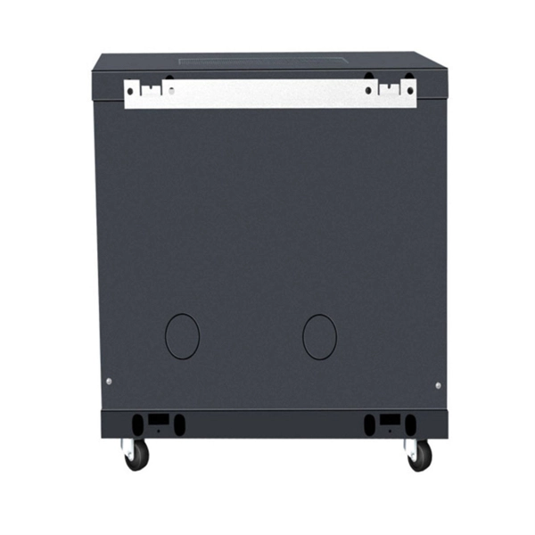
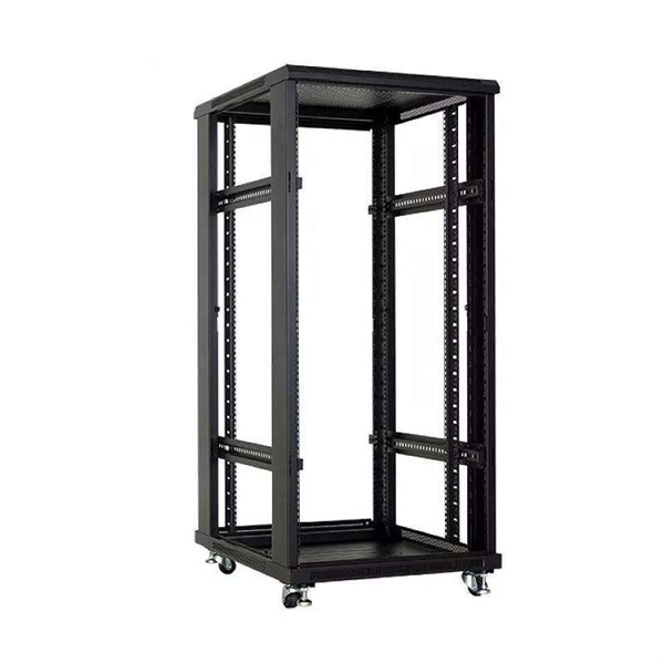
Our guide delivers actionable, step-by-step best practices for rack layout, cable management, and patch panel installation. Following these steps helps you build a clean and efficient structured cabling system that simplifies maintenance and maximizes network performance. Patch panels are one of the best ways to manage an expansive local area network (LAN) by providing quick and easy access to the ports and connections that connect them altogether. Before a single cable is. H. Use cabinet screws to fix the network patch panel to the network cabinet. Note the wiring sequence on the patch panel when wiring, as T568A and T568B have different sequences. Different brands of patch panels may also have different wiring sequences, so always pay attention to the sequence. A patch panel is a board that houses multiple network ports. It acts as a bridge between incoming and outgoing Ethernet cables. Instead of plugging and unplugging devices directly from network switches, you connect them to the patch. Patch panels are a crucial component in any network infrastructure, providing a centralized location for managing cables and connections. By using patch panels, network administrators can simplify cable management, improve network scalability, and reduce downtime. This innovative tool combines precision with automation, ensuring accurate network documentation for IT professionals and network administrators.
[PDF]

Scattering accounts for the greatest amount of attenuation in a fiber cable, between 95 and 97 percent. Light traveling through the fiber interacts with the densities as shown in the light and is then partially scattered in all directions. Fiber optic cables have many advantages, but one of the downsides just like with copper cable, is that it can experience what is called attenuation. Attenuation refers to the loss of light as it travels down the fiber. This can be due to a variety of factors: scattering and absorption, intrinsic. This attenuation is inevitable, so the smaller the attenuation value, the longer the transmission distance of the same optical power. The better the quality of this fiber patch cable. It indicates the amount of signal reflected back. At TREND Networks, we are frequently asked how much loss is allowed when conducting testing on fiber optic cabling. Unfortunately, it is not a simple answer and depends on several factors. So how do you determine acceptable loss? When testing fiber optic cabling, determining acceptable loss is. Understanding fiber loss is vital in maintaining a reliable, efficient network. Understanding it is crucial for anyone involved in data centers, telecommunications, or enterprise networking. Here are the details and instructions about each field and how they contribute to the calculation: 1. Attenuation Coefficient (dB/km): This value represents the inherent signal loss per kilometer of.
[PDF]

An MPO fiber optic patch cord is a multi-core fiber pre-terminated patch cord that uses an MPO connector, mainly used for rapid connections between devices in high-density fiber optic cabling systems. Fiber cores are the heart of fiber optic cables, transmitting light signals that carry data. Made from either high-quality glass or plastic, the core plays a critical role in determining the cable's performance. The total number of cores for a 1pc fiber patch cable is calculated as the number of. Connecting fiber optic cables to patch panels may seem like a straightforward task, but improper connections can lead to signal loss, decreased network efficiency, and even costly repairs. That's why understanding the proper techniques and tools for this process is essential. In this post, you'll. The number of optical cores in an optical fiber is the total number of equipment interfaces multiplied by 2, plus 10% to 20% of the spare quantity, and if the communication mode of the equipment has serial communication and equipment multiplexing, you can reduce the number of cores. They realize high-density, high-efficiency fiber optic interconnection solutions through multi-core fiber connection technology. This article will comprehensively.
[PDF]

Mainly 9steps: Step 1: cut cable with cutting machines in lengths Step 2: put the connector spare parts on the cable Step 3: Strip cable jacket, coating till bare fiber, and make all parts in ready Step 4: Insert fiber into ferrule, glue dispenser and heat oven Step 5:. Mainly 9steps: Step 1: cut cable with cutting machines in lengths Step 2: put the connector spare parts on the cable Step 3: Strip cable jacket, coating till bare fiber, and make all parts in ready Step 4: Insert fiber into ferrule, glue dispenser and heat oven Step 5:. Learn how to make a fiber optic patch cord step by step, from preparation to testing, for reliable high-performance connections. Most guides on making fiber optic patch cord 1 s feel incomplete. They often focus on the final assembly steps, leaving the foundational stages a mystery. From cable cutting to connector assembly and testing, you will gain valuable insights into the production of. Fiber optic patch cords and Pigtails are very important passive fiber optic components in fiber optic networks. Use the fiber optic cleaver to cut the. This document describes the installation and use of the mode-conditioning patch cords listed in Table 1. A mode-conditioning patch cord is shown in Figure 1 IEEE 802. 3z-compliant optical fiber assembly consisting of a single-mode fiber permanently coupled off-center to a 62. 5-micron multimode.
[PDF]
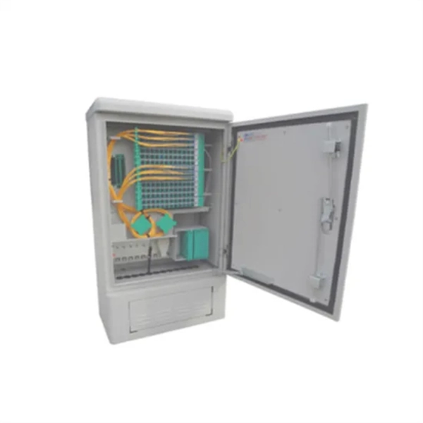
They function as junction points that manage, protect, terminate, and distribute fiber optic cables, ensuring efficient data transmission between different network elements. Fiber Distribution Boxes (FDBs) are critical components in modern telecommunications infrastructure, particularly in fiber optic networks. Whether you're a network technician, IT professional, or simply looking to understand fiber optic networks. A fiber distribution box (FDB) is a passive enclosure that provides secure splicing, termination, and distribution of optical fibers. It typically contains splice trays, adapters, and cable routing components to manage fiber connections. FDBs are used to organize incoming and outgoing cables. Discover Fiber Distribution Hubs (FDHs), fiber cabinets, and other outdoor cabinet solutions by CommScope. Efficiently manage your network with our reliable fiber optic distribution cabinet solutions.
[PDF]

The SS64S16A (L-16. 2,SC) is a Huawei high-performance STM-16 optical interface board designed to deliver 2. 5 Gbps long-haul transmission across SDH transport networks. The SFP-FE-SX-MM1310 (part number: 02315233) is a Huawei-certified 100M optical module. However, the Vendor Name field displays the original manufacturer name, instead of HUAWEI. Huawei. Optical modules are widely used in switches, network interface cards (NICs), routers, and other communication devices. During use, reading optical module information helps understand its real-time operating status, enabling faster troubleshooting of link abnormalities. The following uses the. Original SFP Huawei GPON-OLT-CLASS-C+/C++ Optical Module GPON Optical Module A GPON optical module is connected to one SC optical fiber to provide GPON access service. Return Material Authorization (RMA) Process Standard Hardware Warranty Policy: Original new sealed ZTE product: 1 Year The Support. Problem: All optical ports cannot be connected, and the indicator lights are not on. Solution: To solve this problem, you can follow these steps: Check if the fiber and optical modules are compatible. Perform a. Huawei GPON boards include GPON, XG-PON, XGS-PON, XG-PON&GPON Combo, XGS-PON&GPON Combo interface board, so there are these kinds of GPON optical modules corresponding. The following figure shows the optical modules supported by the S5720-12TP-LI-AC. You can also use the Hardware Center to query the.
[PDF]

You can plug various networking devices into an SFP (Small Form-factor Pluggable) port, such as fiber optic transceivers, gigabit Ethernet modules, and SFP modules. These can include devices such as switches, routers, network interface cards, and media converters. SFP (Small Form-factor Pluggable) is a compact, hot-pluggable network interface module used to connect network devices (switches, routers, firewalls) to fiber optic or copper cables. An SFP interface on networking hardware is a modular slot for a media-specific transceiver, such as for a fiber-optic cable or a copper. Optical transceivers are compact, hot-pluggable devices that convert electrical signals into optical signals, enabling high-speed data transmission across switches, routers, and other networking equipment. Transceiver compatibility is a key concern in enterprise network deployments. Can the sfp interface be plugged. SFP modules function by converting electrical signals from a switch or router into optical or copper signals that can travel through various transmission media. They are inserted into SFP ports found on networking hardware and come in multiple variants to support different cable types, distances.
[PDF]
Choose an SFP module based on the fiber optic cabling that will be connected to the network switches. In addition, fiber cables can transmit data over several kilometers without signal degradation, making them ideal for connecting switches in large campus networks and between different buildings. As they do not emit electromagnetic signals, they're difficult to tap and secure against eavesdropping. Most modern SFP transceiver modules. Hi Experts, I have a basic knowledge of network and need some help. I need to connect 4 Floor Building with 4 Cisco 2960 - 48 ports switch each other and it needs to be through a fiber. So all PCs connected to each switch would reach the LAN/WAN from the other switch. (attached is the image here. Fiber optic cabling is increasingly used to connect network switches and other datacom equipment, especially in long-distance and mission-critical applications. Fiber provides: Increased internet signal bandwidth. Another way is to put a switch at Location B and interconnect using SFP modules. But is it possible to connect AB and BC cables using fiber optic patch cords ? Will it work in this fashion ? If this can work, I. We can use either the cat6 cable or fiber optical cable to link two network switch. One of the advantages of fiber optical cable is its fast speed. In this video, you will see how to link two network ports together to achieve 2G bandwidth between the switches. You even can connect more.
[PDF]