
Relay protection is the discipline of designing schemes that detect faults, coordinate relays, and isolate equipment without outages. It emphasizes selectivity, coordination, fault response, and system behavior rather than individual relay devices. Relay protection is often misunderstood as a. A protective relay is an intelligent electrical device designed to detect faults in power systems and initiate corrective actions such as tripping a circuit breaker. : 4 The first protective relays were electromagnetic. This document provides recommendations, background and philosophy on relay protection that is not available in M07. The facilities to which this Document applies are generally comprised of the fol-lowing: In analyzing the relaying practices to meet the broad objectives set forth, consideration must. What is a Protective Relay? A protective relay is an intelligent device that senses abnormal electrical conditions, such as overcurrent, under-voltage, or frequency deviations. It initiates the operation of circuit breakers to isolate the affected section. This prevents damage to equipment, reduces. Protective relays and devices have been developed over 100 years ago to provide “lastline”of defense for the electrical systems. They are intended to quickly identify a fault and isolate it so the balance of the system continue to run under normal conditions. The selection and applications of.
[PDF]

Protective relays are special electrical devices used to detect faults in power systems and quickly disconnect faulty parts to prevent damage. These relays sense abnormal conditions like overcurrent, under-voltage, or short circuits and send a signal to circuit breakers to open the. Electromechanical protective relays at a hydroelectric generating plant. The relays are in round glass cases. The rectangular devices are test connection blocks, used for testing and isolation of instrument transformer circuits. In electrical engineering, a protective relay is a relay device. Protective Relay Definition: A protective relay is an automatic device that senses abnormal conditions in electrical circuits and triggers actions to isolate faults. Types of Protective Relays: Protective relays are categorized by their mechanism (electromagnetic, static, mechanical) and function. Combines protection, sensors, control power, and circuit breaker in a single package Typically added to a breaker close circuit to prevent accidental reclosure after a trip. Three fundamental components required for each circuit breaker. It initiates the operation of circuit breakers to isolate the affected section.
[PDF]

The K factor (or zero-sequence compensation factor) adjusts the measured impedance for the phase-to-ground fault loop by accounting for the contribution of zero-sequence currents. This compensation is critical because zero-sequence current introduces an offset in the fault impedance. The protection and control devices in electrical equipment can be referred to by numbers, with appropriate suffix letters when necessary, according to the functions they perform. These numbers are based on a system that is adopted by a standard for automatic switchgear by Institute of Electrical. The following Terms are used in protective relaying: 1. Fault Clearing Time 5. Drop Out or Reset value 8. Sealing Relay or holding Relay 10. Time-graded protection is implemented using overcurrent relays with either definite time characteristic or inverse time characteristic. The operating time of definite time relays does not depend on the magnitude of the fault cur-rent, while the operating time of inverse time relays is shorter the. Displaying title 47, up to date as of 5/06/2026. Title 47 was last amended 4/30/2026. There have been changes in the last two weeks to Part 90. Without proper. Also principles of various protective relays and schemes including special protection schemes like differential, restricted, directional and distance relays are explained with sketches. The norms of protection of generators, transformers, lines and capacitor banks are also given. The procedures of.
[PDF]
During an ERG eye test, specialized equipment measures your retina's response to light stimulation. The test uses electrodes, typically in the form of contact lenses or small threads, to record the electrical activity generated by your retina's cells when exposed to different light. The electroretinogram (ERG) is a diagnostic test that measures the electrical activity of the retina in response to a light stimulus. The ERG arises from currents generated directly by retinal neurons in combination with contributions from retinal glia. Importantly, the ERG is an objective measure. Electroretinography, commonly referred to as an ERG test, is a specialized diagnostic procedure used to evaluate the function of the retina—the light-sensitive tissue at the back of the eye. By measuring the retina's electrical responses to light stimuli, this retinal function test plays a crucial. As an essential component of optical fiber communication, optical modules are optoelectronic devices that facilitate the conversion between optical and electrical signals during the transmission process. These cells are known as rods and cones. They form part of the back of the eye known as the retina. The electroretinogram (ERG) is to the retina what the electrocardiogram (ECG) is to the heart. Just as an ECG is crucial to diagnosing illness and monitoring the heart's function, ERG plays.
[PDF]
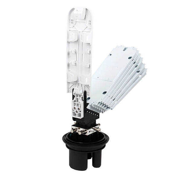
A fiber distribution box (FDB) is a passive enclosure that provides secure splicing, termination, and distribution of optical fibers. It typically contains splice trays, adapters, and cable routing components to manage fiber connections. FDBs are used to. What is a Fiber Optic Distribution Box? A fiber optic distribution box, also known as a fiber optic terminal box or fiber optic termination box, is a device used to connect and manage fiber optic cables in a network. It serves as a central point for fiber optic cable termination, splicing, and. What is a Fiber Optic Termination Box? The Connection Hub at the End of the Fiber Cable A Fiber Optic Termination Box is a small enclosure located at the terminal end of the fiber where it enters your customer premises. Its function is primarily to splice, secure, and protect the optical fibers. In modern FTTH (Fiber to the Home) and optical communication networks, three types of fiber distribution products are widely used: Splitter Distribution Box, ODF (Optical Distribution Frame), and Fiber Terminal Box. They function as junction points that manage, protect, terminate, and distribute fiber optic cables, ensuring efficient data transmission between different.
[PDF]

Our customers can count us for buying Electrical Cable Tray, Ladder Cable Tray, PVC Cable Tray, Mild Steel Cable Tray, Perforated Cable Tray, Raceway, Stainless Steel Cable Tray In Azerbaijan. We have our exceptional range designed and. Looking to buy a Cable Tray in Azerbaijan? Jeetmull Jaichandlall (P) Ltd. is one of the trustworthy Cable Tray Manufacturers in Azerbaijan that is here to fulfill all your wire mesh and netting tools needs. We believe in building fruitful business partnerships. Ltd is the one you can reach. We have a highly experienced team, well-loaded manufacturing unit and a lot more to match up the ever-evolving needs of our customers. Being one of the. Started back in 1983, Cable House is a recognized name engaged in manufacturing and supplying wide range including Hose Clamps, Cable Ties, Crimping Tools, Cable Tray, Industrial Connectors and more, to the national as well as the international market. With our manufacturing expertise, we have even. Micro Sheet Crafts have been involved in offering a wide range of storing systems and solutions, as per the requirements of the customers. Our range is customized and passes stringent quality tests, before.
[PDF]
A dedicated fiber line typically provides businesses with dedicated Internet access, delivering a private, high-speed connection through fiber-optic cables. Unlike shared networks that divide bandwidth and cause slowdowns, it guarantees consistent performance with symmetrical upload and download. What Is Dedicated Fiber Internet? Dedicated fiber internet is a type of internet service that uses fiber optic cables to provide a dedicated and exclusive connection to a user. This means the connection is not shared with other users, resulting in faster and more reliable speeds. Dedicated fiber. Dedicated Fiber, also known as dedicated internet access (DIA), is a premium internet service that provides businesses with a direct fiber optical connection to the internet. It caters to the needs of those who demand the best online performance. Unlike shared broadband services, where multiple users draw from the same network capacity, dedicated fiber provides guaranteed bandwidth that is. When you have a dedicated internet line, it implies a confidential link between your office and the Internet Service Provider. With a dedicated line, you always get exactly what you pay for. Unlike traditional broadband that shares capacity amongst multiple users, leased lines offer what's.
[PDF]

They provide cost-effective solutions through automated dispensing and streamlined production. With the durability, robust IP67-rated protection, and resistance to vibration and environmental factors, these boxes deliver reliable performance in harsh conditions. A distribution boxes is an essential device that manages the safe and efficient flow of electrical power throughout different areas of a building or facility. It is commonly used in homes, offices, and industrial settings to control and protect electrical circuits. Understanding its significance. Many people think distribution boards and distribution boxes are the same, but they're not. They may sound similar, but they have different roles in electrical systems. Knowing the difference helps you choose the right one for your needs. But how do you choose the right one for your application? In this article, we break down the key types, core functions, and selection tips to help you make an. A distribution box, also known as a power distribution box or electrical distribution box, is used to distribute electrical power safely to multiple circuits. It helps organize, protect, and control electrical connections in residential, commercial, and industrial electrical systems. What is the distribution box? A. One critical component of a septic system is the distribution box (also called a d box). The D box is a.
[PDF]

The best router for fiber internet is one that matches your plan speed, home size, and how you use your connection. Our top overall pick is the Netgear Nighthawk RS700S, a Wi-Fi 7 router built for multi-gig fiber plans that handles up to 200 devices across 3,500 square feet. Keep reading for a rundown of the best fiber optic internet routers in 2026. After providing you with the general image about the eight best routers for fiber internet. A fiber-optic connection is the best choice for fast home internet as it has a number of advantages compared to traditional copper cables, such as faster speeds and less interference. For budget-conscious. Instead of using your old router, a high-performance Wi-Fi router designed for fiber optic internet will ensure you seamless streaming, online gaming, and remote work all over your space. However, the market is flooded with countless options, making the selection quite overwhelming. During testing, it provided perfect coverage. Amazon eero 6+ mesh wifi router - Supports internet plans up to a Gigabit, Coverage up to 1,500 sq. 5 Gbps, Coverage up to.
[PDF]

Definition: Optical Line Terminal or optical line termination is a device that basically acts as a part of a passive optical network (PON). It is present in the central office of the network and manages the transmission and reception of information across the overall network. Optical line terminal. A GEPON system usually consists of an OLT (Optical Line Terminal) at the service provider's central office and multiple ONU (Optical Network Units) or ONT (Optical Network Terminals) close to the end user as optical splitters. In addition, the transmission between OLT and ONU/ONT adopts an optical. An Optical Line Terminal (OLT) is a fundamental element within optical communication networks, serving as a hub that facilitates the transmission and reception of data, voice, and video services to and from subscribers' locations. It acts as the central point for controlling and managing network. In optical fiber technology, one of the most widely used devices is an optical line terminal, also called OLT. It can transmit and receive data at several hundreds of kilometers without loss. The OLT is responsible for converting incoming optical signals into electrical signals, which are.
[PDF]

A beam splitter or beamsplitter is an optical device that splits a beam of light into a transmitted and a reflected beam. It is a crucial part of many optical experimental and measurement systems, such as interferometers, also finding widespread application in fibre optic. Beamsplitters are optical components used to split incident light at a designated ratio into two separate beams. In its. 📦 For purchasing, use the RP Photonics Buyer's Guide for beam splitters. It provides an expert-curated supplier directory, buyer-focused technical background information, and structured selection criteria to support professional procurement decisions. What are Beam Splitters? A beam splitter (or. Beam splitters come in many different forms, including cube and plate configurations, each with its own unique characteristics and applications. Beamsplitters are good at splitting incoming light in specified ratios, and they are required to precisely control light intensity in experiments and. What Is a Beam Splitter? Types, Uses, and How It Works A beam splitter is an optical device that takes a single beam of light and divides it into two separate beams. One portion passes through the device while the other reflects off it, and the ratio between the two can be controlled by design. This passive device uses a specialized surface designed to both reflect and transmit light simultaneously. The resulting beams are directed.
[PDF]

Terminal block distribution modules, also known as distribution blocks, are essential electrical components designed to efficiently distribute power from a single source to multiple circuits or loads within various systems such as control panels and switchgear. The distribution blocks and device terminal blocks from the FIX block system are available ready to connect in different cross-sections, mounting types, and colors. The FIX blocks can be used straight away and extended as needed. Hardware terminal blocks help connect and arrange electrical wires. It is the modular, finger-safe alternative to open copper busbar systems used in industrial panels since the 1950s. A standard terminal block connects. Our complete, high-performance line of terminal blocks will be the platform for your solution! Your benefits: In various industrial applications and modern building installations, WAGO's TOPJOB® S Rail-Mount Terminal Blocks offer more than just reliable electrical connections. The comprehensive. What are terminal blocks? Terminal blocks are components that feature an insulated outer frame that houses terminals that join two or more wires/cables. In almost all electrical components, machinery and panels you will.
[PDF]

The main switch, or main breaker, controls the entire electrical supply to the distribution box. This large switch allows you to disconnect all power to the building during emergencies or maintenance work. It's typically rated for the maximum current capacity of the electrical. A distribution box, also known as a distribution board, electrical panel, or breaker box, is an enclosure that houses electrical components responsible for distributing electricity throughout a building. It receives power from the main electrical supply and divides it into separate circuits, each. A distribution box is a key part of electrical systems in buildings. It helps control and distribute electricity to different areas. Inside, you'll find parts like circuit breakers and fuses that protect the system from problems like overloads and short circuits. Today, electrical systems are essential for homes and industries. But what exactly is a power distribution box, and why is it so essential in our daily lives? The DB panel board controls the flow of electricity. Distribution boards, often referred to as electrical panels or breaker boxes, serve as the nerve center of any electrical system. Key components of an electrical panel include the main circuit breaker, individual circuit breakers, and bus bars, all playing vital roles in. The power distribution boxes deliver electricity from the main electrical main to other circuits. Main Distribution Board (MDB) 2. Unitized Panel.
[PDF]