
The formula used to calculate cable tray capacity is: Cable Tray Capacity = (Tray Width × Tray Depth × Fill Ratio) / Cable Cross-sectional Area Where: Tray Width is the internal width of the cable tray in meters (or millimeters). Using our advanced cable tray load calculator is simple and ensures your electrical installation meets structural and safety standards. Follow these steps to generate your accurate Bill of Materials (BOM) and engineering report: Step 1: Define System Specifications: Select your cable tray type. Wire Mesh Cable Tray Fill Ratio = Cross section of cable / Cross section of tray According to NEC 392. 9 (B), when using ventilated tray with multi conductor control cable, the sum of the cross sectional areas shall not exceed 50 percent of the interior cross section of the cable raceway / tray. We independently provide precision steel tools, calculators, and expert resources for steel, metalworking, construction, and industrial projects. I'm here to tell you, it's simpler than you might think, and it makes a huge difference. This guide will walk you through how to work out those loads. An overloaded cable tray can lead to structural failure, causing damage to cables and potentially resulting in costly downtime and safety hazards. Divide this by the cross-sectional area of a single cable to find the.
[PDF]
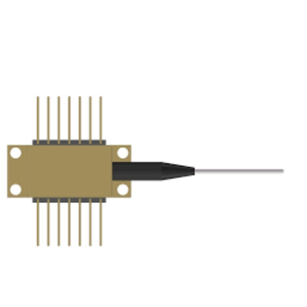
Optical data couplers are essential components in modern fiber optic networks. They enable the connection and distribution of light signals between fibers, facilitating high-speed data transmission over long distances. As digital communication demands grow, these devices become increasingly vital. Explore the role, types, and applications of fiber optic couplers in telecommunications and data networks in our in-depth article. They serve an essential role in managing the flow of light. A coupler is an optical device that combines or splits optical signals. Couplers can be used to split an optical signal into multiple signals, combine multiple signals into a. The same kind of device is useful in fiber interferometers, also for combining two inputs. (Note that polarization issues might occur. Unlike active devices like switches or transceivers, couplers require no electrical power to function.
[PDF]
The Aggregation Switch has a 160 Gb/s switching capacity with a 119. 04 Mpps forwarding rate, features steel construction with a fanless design, and can be rack mounted using the included kit. An Aggregation or "Top-of-Rack" switch is designed to connect everything in a rack at high speeds, then have an even bigger pipe out to the rest of the network. Power Consumption A 32-port, Layer 3 switch made for high-capacity 10G SFP+ and 25G SFP28 connections. The three layers of a traditional three-layer network design are the core layer, aggregation layer, and access layer. As the physical part of the aggregation layer, aggregation switches typically play a. IEEE 802. 3ad link aggregation enables you to group Ethernet interfaces to form a single link layer interface, also known as a link aggregation group (LAG) or bundle. The LAG balances. What is an Aggregate Switch? Understanding Centralized Network Management An aggregate switch is a high-capacity network switch that consolidates connections from multiple access switches, acting as a central point for managing network traffic and providing enhanced bandwidth capabilities. It is. Switch aggregation, also known as link aggregation or trunking, is a method used in computer networking to combine (aggregate) multiple network connections in parallel. This arrangement increases throughput beyond what a single relationship could sustain, offers redundancy in case one of the links.
[PDF]

Understanding how to properly place and use an optical splitter is essential for optimizing signal quality and ensuring seamless data transmission. Let's explore the best practices for deploying this crucial component. What is An Optical Splitter?. A fiber optic splitter is a passive optical component that divides a single incoming optical signal into two or more outgoing signals, or combines multiple incoming signals into one. Unlike active devices (which require power), splitters operate without electricity, relying solely on the physics of. Where splitters are placed in the network can make significant impacts on fiber counts, network cost and deployment time and operational steps, such as customer onboarding and maintenance. One important note is that splitting architectures should be seen as tools that can be mixed and matched to. In the realm of optical communication networks, the optical splitter serves a vital role in dividing and distributing optical signals efficiently. You use optical couplers and splitters to split or join signals in fiber networks. These devices help you control light signals well. You can also use them to join light from. This guide will demystify this pivotal passive device, exploring its types, working principles, and how it seamlessly integrates with optical transceivers to bring high-speed internet to your doorstep.
[PDF]

This report lists the top Sri Lanka Telecom Tower companies based on the 2023 & 2024 market share reports. Mordor Intelligence expert advisors conducted extensive research and identified these brands to be the leaders in the Sri Lanka Telecom Tower . Monopole towers are constructed from steel or concrete and can range in height from 30 meters to over 100 meters. It is a type of lattice tower that is commonly used in areas where space is limited or aesthetics are important, such as urban or suburban environments. Need More Details on Market Players and. We are an integrated service provider in Telecom, Energy and Civil Infrastructure. Our capabilities range from providing end to end services for telecom tower construction, technical enhancements and maintenance on the towers. We also provide renewable energy solutions and have strong expertise. SGH TowerCo Ltd., the telecommunications and network infrastructure arm of Supreme Global Holdings (SGH), has announced that it has been officially granted a Telecommunications Infrastructure Services Licence by the Telecommunications Regulatory Commission of Sri Lanka (TRCSL). Preview of Communications tower businesses in Sri Lanka **. **** Athurugiriya Clock T. **** Sri Lanka 🇱🇰🇯🇵🌄🌍🌻. **** ITN. We are the pioneers in providing lightweight aluminum rooftop modular tower solutions from Europe.
[PDF]
There are several factors that can impact the cost of a dedicated internet line. Some of them are out of a customer's control, but some are not. Understanding these factors can help businesses make informe.
[PDF]

Optical Network Terminals (ONTs): Often called "fiber boxes," ONTs are located inside homes and connect the fiber optic cable to the internal network. They receive the optical signal from the external fiber optic cable and convert it into a usable signal for home networking equipment. A fiber optic junction box, also known as a fiber optic distribution box or termination box, is a protective enclosure that facilitates the connection and management of fiber optic cables. It serves as a central point for organizing and distributing optical fibers, ensuring efficient connectivity. A Fiber Terminal Box (FTB) is a customer-side termination and distribution device used at the end of the optical network. Key Functions Typical Applications ZION FTB Highlights In essence: The Fiber Terminal Box is an end-user termination device for small-scale distribution. ■ What Is a Fiber. Fiber junction boxes play a crucial role in the organization, protection, and distribution of fiber optic cables in various applications, including telecommunications, data centers, and industrial networks. Primary Purpose: Its core function is to provide a secure, protected location. To handle a large number of optical fibers with lower cost and higher flexibility, various optical junction boxes are widely used to connect and arrange optical fibers. The distribution box provides.
[PDF]

At Least Three to Six Feet Away: A commonly suggested distance for minimizing RF exposure is three to six feet (approximately 1-2 meters) from your bed. If possible, aim for six feet or more, especially if you are sensitive to electromagnetic fields (EMFs). The safe distance from a WiFi router depends on the router's power and the level of exposure you are comfortable with. Here are some general guidelines: Minimum Distance: Experts recommend maintaining at least 10 feet (3 meters) from a WiFi router to reduce radiation exposure significantly. Ideal. Keep the router away from high-traffic areas like bedrooms, nurseries, or places where you spend long periods. We typically recommend at least 10 feet away from where you spend most of your time. Instead, place it in a location where it can still emit sufficient coverage but minimize unnecessary. While there are no strict guidelines, most experts recommend keeping a reasonable distance between your WiFi router and sleeping area. Some studies have pointed to a higher risk of sleep disturbance, decreased cognitive function, and even potentially cancer with prolonged proximity to WiFi radiation. Dual-band routers emit signals on 2. At these distances, RF exposure drops to low or minimal levels while maintaining reliable connectivity. For maximum protection during sleep, position your router.
[PDF]

In this comprehensive guide, we'll walk through the best practices for installing various types of fiber optic cable, from patch cords to distribution fiber, and provide practical tips to ensure a successful installation. This article will guide you through the necessary tools, materials, and methods on how to connect fiber optic cables effectively, ensuring you achieve optimal performance from your fiber optic network. Have a network installation project? Fiber Optic Cables: The primary medium for your connections. Fiber optic cable is a type of cable that contains one or more optical fibers—thin, flexible strands of glass or plastic that are designed to transmit light signals. These cables are used for transmitting data over long distances with high bandwidth and low signal loss. Before connecting any fiber cable, you need to assemble the proper preparation tools: With the right tools in hand, follow these key steps to achieve reliable fiber connections: 1. The number one cause of signal loss in optical fiber installations is dirt on. In this video, we'll guide you through preparing and terminating fiber optic cables using SimplyFiber products, known for their high quality, ease of use, and reliability. more Audio tracks for some languages were automatically generated. Why Opt for Fiber Optics? Fiber optic cables have skyrocketed in.
[PDF]

A fiber pigtail is a short optical fiber cable with a connector pre-installed on one end and a bare fiber on the other. It acts as a bridge between optical fibers and devices, making it a vital part of network termination, splicing, and patching processes. In the world of fiber optic communications, reliability and precision are everything. As networks scale to support FTTH rollouts, 5G base stations, and hyperscale data centers, the way fiber is terminated and managed at every endpoint can determine whether a project succeeds or fails. One component. Executive Summary: A fiber optic pigtail is one of the most commonly specified yet least understood components in structured cabling. Get the wrong connector type, the wrong polish, or skip proper fusion splicing technique—and you're looking at elevated signal loss, increased back reflection, and a. ■ What is a fiber optic pigtail cable? A pigtail fiber indicates a short length of optical fiber cable that has a pigtail connector (for example, SC, FC, ST, LC, etc. ) fitted on one end and the other end undressed (for connection through fusion or splicing) to the main fiber optic cable. What does fiber optic pigtail mean? A fiber optic pigtail works like a bridge between two different connection methods. It is usually suitable for field termination using a mechanical or fusion splicer.
[PDF]

