
Creating a 90-degree elbow in an electrical cable tray, often called a "fabricated" or "mitered" bend, involves cutting, bending, and fastening a straight section of tray. The most common method involves creating two 45-degree cuts to form a 90-degree angle. Use this tool to estimate sloped section length, horizontal run requirement, cut marks, and installation feasibility. Measure this distance along the straight tray. Depends on the type of cable tray, you can buy 90° tray fittings or use a speed square with a straight edge and a grinder or skill saw to cut 45° cuts. Do you want a hard 90 or 2 spaced out 45° bends? Need dimension of tray first width x side wall. Also need to know if you're bending inside or. Key Concept/Formula: To create a 90-degree turn in a cable tray, a mitered joint is used, which involves cutting two pieces of cable tray at a 45-degree angle each. Key Concept/Formula: For a precise 45-degree cut, if the width of the. By applying the following formula you can quickly find the size of cut out section that you need to cut out of the side of the cable tray, or gutter-type section to make that angle. First, you have to find (C) which is found by dividing 90° by (B) 22° = 4. You can then calculate the size.
[PDF]
Flex electrical cable, often referred to as flexible cable or flex, is a type of wire that is designed to withstand repetitive bending and movement without damage. Article 400 covers the general requirements and applications for flexible cords as contained in Table 400. A “flexible cord” is two or more insulated conductors enclosed in a flexible covering. Figure 01 The NEC does not. What is a flexible cable? Flexible cables are cables that have multiple conductors (Class 5 or Class 6 conductors) that form the conductor and are insulated and sheathed in a lightweight, flexible material (usually plastic or rubber). Why choose flexible cables for domestic use? It is suitable for. These include flat flexible cable (FFC), stranded wire, power cables, control cables, and flexible electrical conduit. Each type meets specific needs across industries like automotive, electronics, and medical devices. Here is a quick look at how leading cable types are used worldwide: You can. Power distribution cables present a unique challenge to electrical wire interconnect system engineers. Unlike rigid electrical wiring, which is designed for static installations within buildings, walls, or. In any electrical system—whether powering lights in homes, machinery in factories, or robots in operation—cables are the unsung heroes, safely and reliably transmitting electrical energy. As the backbone of power distribution systems, cables connect power sources (such as circuit breakers) to.
[PDF]

Whether you are a home user, managing a small office, or running a business network, this guide will walk you through connecting your ONT to your router, configuring your network, and optimizing your Wi-Fi for smooth performance. However, setting up a fiber optic connection to your router can seem daunting if you're unfamiliar with the process. In this guide, we'll walk you through how to connect a fiber optic cable to a router safely and efficiently. Why Use Fiber Optic Internet? Before diving into the setup, let's quickly. Setting up a fiber internet connection requires understanding key hardware components and following a specific connection sequence to establish your home network. The fiber. Fiber optic internet delivers lightning-fast speeds, reliable connections, and low latency for streaming, gaming, video calls, and more. Setting up your fiber router correctly ensures you get the most from your connection. This comprehensive guide combines industry standards with field-tested practices to ensure you achieve a rock-solid. In this guide, we'll explain router compatibility, setup steps and whether upgrading your router is necessary to maximize fiber speeds. Here's a simple guide to help you through the process: 1. Check Your Fiber Optic Equipment Before you start, make sure you have the necessary equipment: Fiber Optic Modem (ONT – Optical Network Terminal):.
[PDF]

The National Electrical Code (NEC) does not specify the maximum distance for a ground rod from a panel. However, the ground rod should be placed as close as possible to the panel to ensure an effective ground connection. Electrical clearances set the minimum safe distances for panels, overhead lines, pools, and buried wiring — and ignoring them has real consequences. (If these areas are accessible to other than pedestrian traffic, then one of the other conditions applies). Above finished grade or sidewalks, or from any platform or projection from which they. Learn key electrical code requirements for junction boxes, including sizing, grounding, materials, and clearance to ensure safety and efficiency. Whether it's a. The National Electrical Code (NEC) provides comprehensive safety standards for electrical installations, including requirements for electrical panels (main service panels and subpanels or breaker box). NEC Article 408 covers switchboards, switchgear, and Panelboards installation and applications. Following the manufacturer's installation instructions for the ground rod and.
[PDF]

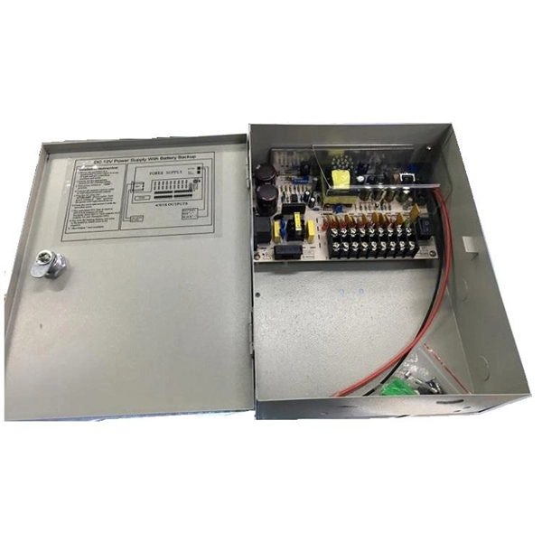
This guide shows you how to organize circuit breaker wiring properly. You will learn to build a safe, efficient, and professional electrical system today. Circuit breaker wiring configurations involve organizing main switches, busbars, and branch breakers within a distribution box. While some homeowners may attempt this, it's highly recommended to hire a qualified, licensed electrician for circuit breaker box wiring. This is a complex and potentially dangerous task that involves working with high voltage electricity. Mistakes can lead to serious injury, fire, or damage to. A breaker box, also known as a circuit breaker panel, is an essential component of any electrical system. It is responsible for distributing electricity throughout a building, ensuring that each circuit receives the proper amount of power. To understand how a breaker box works, it is helpful to. When installing or troubleshooting a power distribution system, understanding how to correctly connect the main electrical supply to the control panel is crucial. The first step involves running a dedicated cable from the incoming supply to the distribution panel, ensuring it is rated for the load. How to read these diagrams. This page contains wiring diagrams for a service panel breaker box and circuit breakers including: 15amp, 20amp, 30amp, and 50amp as well as a GFCI breaker and an isolated ground circuit. Messy distribution boxes are dangerous and very hard to fix.
[PDF]
In this guide, we'll break down the key wiring layout, main control panel components, and how everything connects — from the main power isolator to the PLC and sensors on the production line. Every roll forming machine relies on a precisely designed electrical control and wiring system. This system ensures that motors, sensors, drives, and. This guide will walk through the key points you need to consider when preparing electrical schematics and wiring diagrams for a roll forming machine. This guide breaks down the entire electrical system of a modern roll forming machine — from incoming 3-phase supply to flying shear synchronization — with: A complete roll forming electrical system contains: Roll forming machines are typically built for: Voltage mismatch damages VFDs, transformers. Electrical design is the backbone of any roll forming line. Electrical design is the backbone of any roll forming line. These machines convert metal coil.
[PDF]

Start by separating your Ethernet cable into two separate cables and connecting them to the back of the Ethernet cable splitter. Once the cables are securely connected, connect the other ends to your desired devices. Ensure that the cables are tightly secure and that all connections. When you need to connect multiple wired devices like computers, printers, and IP phones, but only have one Ethernet wall port, using an Ethernet splitter or network switch can expand your connectivity without rewiring. This guide explains your options and helps you choose the best solution for your. An Ethernet splitter is a small device that allows two Ethernet-connected devices to share a single cable run. It does not increase speed or create extra bandwidth. It simply divides signal pairs. This tool works best in basic setups where running another cable is not possible. An Ethernet splitter. Ethernet cable splitter wiring diagrams are essential for anyone who needs to connect multiple devices in a home or office network. With the ever-increasing popularity of high-speed internet and streaming services, providing reliable connections to multiple devices is becoming increasingly. An Ethernet splitter doesn't actually split a single Ethernet connection to provide separate internet access to two devices. Instead, it utilizes only two of the four pairs of wires within a single Ethernet cable to connect two devices, requiring two splitters for the setup to function correctly.
[PDF]
In this video, you will learn: The essential components of a distribution board, including MCBs (Miniature Circuit Breakers), RCDs (Residual Current Devices), and busbars. How to safely connect incoming and outgoing cables to the DB box. The importance of earthing and. A distribution box is the heart of any electrical system. It takes the incoming power and safely distributes it to different circuits throughout your building. Whether in a home or an industrial facility, this box keeps your electrical setup organized, functional, and efficient. The distinction between 1P and 2P circuit breakers plays a pivotal role in determining the appropriate protection level for various circuits. In case of high power use, to meet the demand of currentAnd in order for the current to be carried at the demanded high powers to be met, the method of parallel connection of the cables can be selected. And when this method is selected, multiple cables need to be used for each phase. In the event. Welcome to our channel @Electricalgenius In this video, we'll take you through a detailed step-by-step guide on wiring a home distribution DB (Distribution Board) box. And all the switching and protective devices are installed in the distribution box. Single Phase Distribution Box generally consists of Double Pole MCBs, Single Pole MCBs, and RCCBs.
[PDF]

On the US market, a 5. 26 mm 2 (10 AWG) ground wire must be used, and in all other markets a 6 mm 2 must be used. Grounding of the units: Attach a ground wire from one of the threaded studs (A) at the bottom of the housing, to the mounting plate (B). Power from factory ground must be installed by a qualified electrician. Each DISTRIBUTION BOX and controller must be grounded. Whether you're a seasoned pro or just starting out, this comprehensive guide will give you practical. To define the technical specifications for the supply of Fibre Optic Overhead Ground Wire (OPGW) for installation on extra high voltage power lines, under the responsibility of Tasmanian Networks Pty Ltd (hereafter referred to as 'TasNetworks'). This standard applies to all OPGW purchased for. 4. FO-VC2 JOINT USE - VERICAL MIDSPAN CLEARANCES 48. FO-GB GROUNDING AND BONDING 49. FO-RI JOINT USE RISER. The requirement includes the design, supply, stringing and splicing of OPGW cable on 400KV, 220KV & 132KV Transmission Towers. This specification defines the design, material, performance and test requirements for fibre optic cable to support the fibre optic telecommunication needs. The work. IPMENT, STRUCTURES, ETC. IN ELECTRICAL STATIONS INCLUDING TRANSMISSION AND DISTRIBUTION SUBSTAT GR THAN 8 FT FROM THE FENCE. THE FENCE SHALL BE GROUNDED SEPARATELY FROM THE GRID UNLESS OTHERWISE NOTED ON THE A PROPRIATE PROJECT DRAWING. FOR FENC G O OUTSIDE CLEARANCE SPACING. SEE APPLICATION.
[PDF]

In this comprehensive guide, we'll walk through the best practices for installing various types of fiber optic cable, from patch cords to distribution fiber, and provide practical tips to ensure a successful installation. This article will guide you through the necessary tools, materials, and methods on how to connect fiber optic cables effectively, ensuring you achieve optimal performance from your fiber optic network. Have a network installation project? Fiber Optic Cables: The primary medium for your connections. Fiber optic cable is a type of cable that contains one or more optical fibers—thin, flexible strands of glass or plastic that are designed to transmit light signals. These cables are used for transmitting data over long distances with high bandwidth and low signal loss. Before connecting any fiber cable, you need to assemble the proper preparation tools: With the right tools in hand, follow these key steps to achieve reliable fiber connections: 1. The number one cause of signal loss in optical fiber installations is dirt on. In this video, we'll guide you through preparing and terminating fiber optic cables using SimplyFiber products, known for their high quality, ease of use, and reliability. more Audio tracks for some languages were automatically generated. Why Opt for Fiber Optics? Fiber optic cables have skyrocketed in.
[PDF]

NEC-compliant grounding wire sizing calculator tool. Please enter a valid service size between 30 and 2000 amperes. The National Electrical Code (NEC) provides clear guidelines for ground wire sizing through Table 250. 122, but understanding how to apply these requirements correctly can make the difference between a safe installation and a costly code violation. Proper grounding conductor sizing is critical for. Calculate proper grounding wire sizes based on electrical system parameters. By fault current and length — considers potential short-circuit currents and conductor distance. By breaker size — quick lookup based on the installed breaker. NEC Ground Wire Size Chart provides standard wire sizing for grounding conductors in electrical systems. This chart is used to size the ground wire that runs with branch circuits and feeders. The second is the Grounding. AFL AlumaCore OPGW (Optical Ground Wire) is preferred for its central aluminum pipe and color-coded fiber optic buffer tubes which simplify the splicing process while providing optimum fiber protection as well as long term product reliability. Optical Ground Wire (OPGW) is a dual functioning cable.
[PDF]

This phenomenon is known as the skin effect. The result is higher electrical resistance, energy loss, and reduced efficiency — particularly problematic for data transmission and high-frequency power applications. Through smart conductor stranding, manufacturers can reduce the. Defective products and waste products of bundled wire and stranded wire, the main problems are over-twisting, inner or outer single wire breakage, lack of strands, single wire or stranded wire surface abrasion, single wire dorsal strand, single wire peeling, scarring, brittle breakage, arching. This phenomenon is known as the skin effect. Through smart conductor stranding, manufacturers can reduce the impact of this effect. Causes of generation. Causes of. Understanding the diverse factors that can compromise cables—mechanical stress, environmental conditions, electrical anomalies, and more—empowers us to prevent, identify, and address issues promptly. By recognizing the importance of cables and the potential risks they face, we can ensure the. Both shielded and unshielded twisted-pair copper cable comes in either stranded or solid wire versions. There are plenty of considerations when it comes to choosing one or the other, including standards, environment, application, and cost.
[PDF]

A junction box contains four trade size 3 raceways: two on the left side, one on the right side, and one on the bottom. Once conductors have to turn, be pulled through, or be spliced inside an enclosure, the box dimensions start affecting installation time, conductor damage risk, and inspection results. A raceway design that looks fine in a panel schedule can still become a problem if the box is too short for an. Pull boxes, junction boxes, and conduit bodies must be sized to allow conductors 4 AWG and larger to be installed without damage to the conductor insulation. The NEC provides sizing requirements in 314. The distance between raceway entries enclosing the same conductor must be at least 6 times the trade. To size a junction box correctly, first decide whether NEC 314. Use box-fill rules for splices and devices, and pull-box rules for large conductors and raceways. The most common mistake is using the wrong. NEC 314. 28 specifies the minimum size requirements for pull and junction boxes in electrical installations. Proper sizing ensures conductors can be installed without damage and allows for proper bending space. How Does the Calculator Work? The calculator uses NEC 314. Minimum Length = 8 × Largest Conduit Size Minimum Dimension = 6 × Largest +.
[PDF]
