Choose an SFP module based on the fiber optic cabling that will be connected to the network switches. In addition, fiber cables can transmit data over several kilometers without signal degradation, making them ideal for connecting switches in large campus networks and between different buildings. As they do not emit electromagnetic signals, they're difficult to tap and secure against eavesdropping. Most modern SFP transceiver modules. Hi Experts, I have a basic knowledge of network and need some help. I need to connect 4 Floor Building with 4 Cisco 2960 - 48 ports switch each other and it needs to be through a fiber. So all PCs connected to each switch would reach the LAN/WAN from the other switch. (attached is the image here. Fiber optic cabling is increasingly used to connect network switches and other datacom equipment, especially in long-distance and mission-critical applications. Fiber provides: Increased internet signal bandwidth. Another way is to put a switch at Location B and interconnect using SFP modules. But is it possible to connect AB and BC cables using fiber optic patch cords ? Will it work in this fashion ? If this can work, I. We can use either the cat6 cable or fiber optical cable to link two network switch. One of the advantages of fiber optical cable is its fast speed. In this video, you will see how to link two network ports together to achieve 2G bandwidth between the switches. You even can connect more.
[PDF]

The management interface is located above the console port on the rear panel of the Mobility Access Switch. It is labeled as mgmt. The management port is a dedicated interface for out-of-band management purpose. When connecting a PC to the Ethernet management port, you must first assign an IP address. Whereas, a Console Port is a serial interface used for direct, local device access via a console cable, typically during initial setup or troubleshooting. This interface is specifically available for the management of the system and cannot be. Right now, it won't, because no device points to the switch's Mgmt. IP as a gateway, but all one would need to do is connect to a port on the Mgmt. VLAN and manually enter the switch IP as a gateway and then you'd be able to route between all four subnets. The solution is to remove the VLAN. You can access and manage the switch using the GUI (Graphical User Interface, also called web interface in this text) or using the CLI (Command Line Interface). There are equivalent functions in the web interface and the command line interface, while web configuration is easier and more visual than. This topic describes how to configure the management port. It includes the following information: You connect the management port to an Ethernet switch or router that is part of your internal local area network (LAN) and that can connect to your network management infrastructure.
[PDF]

One SFP module is inserted into the switch's SFP port, and another module is inserted into the SFP port of the target device, facilitating data transmission through the fiber optic cable. SFP ports are small hot-pluggable module interfaces typically used for connecting fiber optics or copper cables. They support various transmission rates and distances, including 1G, 10G, and higher speeds. SFP modules can be selected based on the requirements, whether it's single-mode fiber for. An SFP port is a physically small slot in a networking device that accepts an SFP module insert. Most modern networking devices, such as Ethernet switches, servers, routers, network interface cards, and fiber media converters, generally have two or more built-in SFP ports. You may connect different. In plain terms, an SFP port on a gigabit switch is the little plug-in hole that gives the switch physical flexibility — the ability to use fiber one minute and copper the next without buying a different switch. Unlike fixed RJ45 copper ports, SFP ports support both fiber and copper modules, enabling far longer distances, greater flexibility, and improved scalability in enterprise. First, to connect SFP modules with fiber optic cables, ensure that the module type matches the line, as there are different modules for single-mode and multimode fiber. Next, insert the module firmly and securely into the SFP port, then attach the cable to the module using the connector. Switches with SFP ports can.
[PDF]

How to Install a Fibre Connector into a Patch Panel (Easy fibre optic connector installation) How to Install a Fibre Connector into a Fibre Optic Patch Panel. How do you install fibre optic connectors?. Connecting a fiber patch panel to a switch is a critical step in setting up a fiber optic network. There are different types of connectors. In today's high-performance networks, fiber optic patch cables are the lifelines that ensure smooth data flow across switches, servers, and routers. Even the most advanced optical transceivers can only perform at their peak when paired with properly installed, clean, and precisely managed fiber. Choose an SFP module based on the fiber optic cabling that will be connected to the network switches. SFP transceiver modules almost always require two fiber optic cable strands. A Fiber Patch cord connects two devices. You plug it into a switch, router, or patch panel. It's ready to use out of the box. A pigtail is for splicing. You fuse it to a. With a railroad switch (patch panel), the train (data) can travel from A to B, C and even more destinations, otherwise it can only go from A to B, or C to D. This article, What Is a Patch Panel Used for?, has explained it thoroughly.
[PDF]

Huawei S6320-SI series switches are Huawei-developed next-generation multigigabit 10GE fixed switches. The S6320-SI can provide high-speed wireless access, and access for 10GE servers in data centers or function as access/aggregation switches on a campus network. As a result, it decreases energy use by over 40% compared to traditional switch systems. The S5730-SI series switches are next-generation standard gigabit Layer 3 Ethernet switches. The S5700-EI series gigabit enterprise switches (S5700-EI) are next-generation energy-saving switches developed by Huawei to meet the demand for high-bandwidth access and Ethernet multi-service aggregation. Based on the cutting-edge hardware and Huawei Versatile Routing Platform (VRP) software, the. S5700-10P-LI-AC Switch is a simplified Gigabit Ethernet Switch with 8*10/100/1000Base-T Ethernet ports, 2 Gigabit SFP, AC powered. The product features the green and energy-saving and provides flexible full Gigabit access and 10 Gigabit uplink ports. Moreover, it features innovative advanced sleep. For small businesses and IT managers juggling tight budgets and limited rack space, the Huawei 10 port switch often emerges as a silent hero. This unassuming device bridges the gap between basic connectivity and scalable network performance, but its true value lies in solving problems most.
[PDF]
The ProCurve Switch 2800 series consists of two switches: the 24-port ProCurve Switch 2824 with 20 10/100/1000 ports, and the 48-port ProCurve Switch 2848 with 44 10/100/1000 ports. In addition, each switch has 4 dual-personality ports for RJ-45 10/100/1000 or mini-GBIC fiber. Manuals and User Guides for HP ProCurve 2848. We have 3 HP ProCurve 2848 manuals available for free PDF download: Function Manual, Install Manual, Datasheet Hp ProCurve 2848 Pdf User Manuals. View online or download Hp ProCurve 2848 Function Manual, Install Manual, Datasheet. I am going to link the following 3 switches, HP Aruba 2920-48 POE, 2510-48 and 2848, by double fibre optic cables (through the miniGBIC slots) so double link from the 2920 to the 2510 and the a double link to the 2848. You can examine HP ProCurve 2848 Manuals and User Guides in PDF.
[PDF]

A mesh network wifi router (with satellites) is the best way to cover your home while overcoming signal degradation because of the walls and floors. Assuming your ISP is cable, wire a receptacle in a closet and pull the cable into the same closet. Plug in the main router there. A fiber-optic connection is the best choice for fast home internet as it has a number of advantages compared to traditional copper cables, such as faster speeds and less interference. Many major ISPs, such as Verizon and Xfinity, offer fiber connections directly to your door, known as FttP or Fiber. But if you want to get the full potential of this internet, invest in a Wi-Fi router that handles its speed and reliability. Put the satellite. Provides a nearly invisible fiber path to directly connect your modem to a computer, TV, or gaming console — no drywall repairs, no tripping hazards, no complaints from your spouse. Two Ethernet to fiber converters are included which allows connection to any devices with Ethernet ports. NEMA 1-15. However, you need a router capable of supporting multi-gig speeds to get fiber internet connectivity. With the many options available on the market, picking the best router for fiber internet can be tricky. Our top overall pick is the Netgear Nighthawk RS700S, a Wi-Fi 7 router built for multi-gig fiber plans that handles up to 200 devices across 3,500 square feet. For budget-conscious.
[PDF]

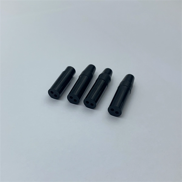
pigtails can be divided into single-mode (colored yellow) and multimode (colored orange) fiber. Multimode pigtails use 62.5/125 micron or 50/125 micron bulk multimode fiber cables and terminated them with multimode fiber optic c. pigtails can be divided into single-mode (colored yellow) and multimode (colored orange) fiber. Multimode pigtails use 62.5/125 micron or 50/125 micron bulk multimode fiber cables and terminated them with multimode fiber optic connectors at one end. 10G multimode fiber cables (OM3 or OM4) are also available in optic pigtails. The jacket color of 10. Fiber Optic Pigtails, In fiber optic cable installation, how cables are attached to the system is vital to the success of network. If done properly, optical signals would pass through the link with low attenuation and little return loss. pigtail offers an optimal way to joint optical fiber, which is used in 99% of single-mode applications. This pos. According to different types of pigtail cable connector terminated at the end, there are LC fiber pigtail, SC pigtail, ST pigtail, FC pigtail, fiber pigtail and so on. With different structures and appearance, each of them has their own advantages in different applications and systems. Let's go through some widely used ones. SC Pigtail: SC pigtail.
[PDF]

The wiring inside the panel is neatly organized with red wires for live connections, black wires for neutral, and yellow-green wires for grounding. At the bottom, there is a terminal block where incoming and outgoing wires are connected. Welcome to this live training session! ⚡ In today's tutorial, I'll be demonstrating how to arrange cables neatly inside a distribution bo. more See what others said about this video while it was live. This switch allows the user to choose the power source. Below the switch, there are several miniature. An electrical panel box, also known as a breaker box or a distribution board, is a crucial component of any electrical system. It serves as a central hub for distributing electricity throughout a building, ensuring that power is delivered safely and efficiently to all the required locations. A neat, well-organized subpanel bundles wires to conserve space and improve access. Ideally, wire groups are installed in layers and wires are bent at right angles to buses or breakers. Label short sheathing sections (slugs) to indicate which circuits wires serve. A distribution box, also known as a.
[PDF]
This comprehensive guide will delve into the best practices for cable removal, the benefits of maintaining a clean cable environment, and step-by-step instructions to ensure the process is efficient and compliant with industry standards. Every new installation means an increased number of low voltage cables that are cut and left in ceilings, floors, and walls. From a tenant or building owner's point of view, removing abandoned cable has. Effective cable removal ensures safety, optimizes performance, and prepares the infrastructure for future upgrades. Before beginning any installation, safety. Fiber-optic cables are the backbone of modern connectivity—powering 5G networks, global internet backbones, and data center interconnections with near-light-speed data transmission. While these cables are engineered for durability (with some rated to last 25+ years), they are not invulnerable. Even. Here are 5 vital rules for staying safe when you're working on fiber optic cables. Know the standards that apply to your work Whether you're installing new fiber optic cables or troubleshooting and repairing an existing fiber network, a working knowledge of the regulations that apply to your. In outside plant fiber optic installations, the biggest cause of network failure is likely to be electronic problems or, if it's in the cable plant, what is usually called “backhoe fade” for buried cables and “target practice” for aerial cables, both of which are self-explanatory.
[PDF]

Optical cables are born from ultra-pure glass preforms, drawn into hair-thin fibers, coated for protection, bundled strategically, and encased in durable jackets. This meticulous process ensures light-speed data transmission with minimal loss. Fiber optic cables are the backbone of today's high-speed internet, telecommunication systems, and data transfer technologies. With the increasing demand for faster and more reliable connectivity, the construction of optical fiber cable factories has become essential. In this guide, we will. The Modified Chemical Vapor Deposition (MCVD) process was developed in 1974 at Bell Labs to improve traditional Chemical Vapor Deposition (CVD) methods for fabricating optical fibers. In MCVD, a quartz tube is used as the initial substrate or source material. Fiber optic technology has revolutionized the way information is transmitted, offering numerous advantages over traditional copper wiring. What makes fiber optic cables special is their ability to. Single-mode fiber represents the pinnacle of long-distance optical transmission technology. At Sinoptec, our advanced manufacturing processes ensure each fiber meets rigorous.
[PDF]
This article is about the Internet Outages Map, which provides a visualization of global internet health over the last 24 hours. It also includes information on how to use this map and what data it collects, as well.
[PDF]

One of the most common ways to test fiber optic cables is with a light source, which emits light through the cable to detect any potential problems. LED light sources emit. Fiber optic cables are a top choice for high-speed communication systems and can also serve as sensors to measure and monitor various quantities. Modern. Document the end-to-end results for the fiber optic segment you just tested. Related: Data Center Cabling Best Practice Guide Using optical time domain reflectometer testing, you'll measure the length of the fiber optic cable, attenuation, and any events occurring on that fiber segment. Events are. A photodiode is a semiconductor diode sensitive to photon radiation, such as visible light, infrared or ultraviolet radiation, X-rays and gamma rays. It produces an electrical current when it absorbs photons. This can be used for detection and measurement applications, or for the generation of. A typical fiber optic communication system consists of three primary components: a transmitter, a fiber optic cable (the transmission medium), and a receiver. The transmitter usually incorporates a Light Emitting Diode (LED) which converts digital binary data into light waves. The studies cover fiber optic components that have standard SMA connectors to couple with SMA-SMA connectorised PMMA (plas otodiode and a phototransistor. It has a built-in optical power meter an the associated power supplies. Apart from LPS04, the accessories.
[PDF]

