This paper will review the development of fiber-optic high-temperature sensors over the last 30 years, presenting their design and fabrication methods according to sensing type and typical temperature measurement performance. The full paper consists of eight sections. Fiber-optic high-temperature sensors are gradually replacing traditional electronic sensors due to their small size, resistance to electromagnetic interference, remote detection, multiplexing, and distributed measurement advantages. This paper reviews the sensing principle, structural design, and. Luna's Optical Backscatter Reflectometer (OBR) products are based on OFDR and provide a level of detail and precision not available with the prevailing fiber optic diagnostic tool - the optical time domain reflectometer (OTDR). OBR systems map out loss along a single-mode fiber (SMF) or multi-mode. breadth and most comprehensive solutions for optical communications test products to be found in one place. Corning's High Temperature Fibers are designed for applications requiring improved fatigue resistance, high usable strength, and excellent resistance to higher temperatures and hydrogen permeation. Thus, wireless communication -situ processing of data would combined with in significantly improve the ability to include sensors into high temperature systems and thus lead toward more intelligent engine systems. NASA Glenn Research Center (GRC) is presently lea, communication systems,ding the.
[PDF]

Managing optical attenuation helps keep your signal safe. Clean your optical connectors so you do not lose. Optical Signal Attenuation is the single greatest factor limiting the distance and performance of your network. Understanding it is crucial for anyone involved in data centers, telecommunications, or enterprise networking. This guide will demystify signal loss, explore its causes, and show you how. In high-speed environments, where the optical link budget is measured in fractions of a decibel, diagnosing and eliminating unexpected loss is the network engineer's most critical task. This field guide provides a systematic, step-by-step approach to troubleshooting and resolving the most common. Signal loss in Fiber Optic networks can make data slow. It can also break your connection. You should fix it fast to get speed and stability back. > You can solve this with simple steps. Signal Degradation (Loss of Light) When the signal quality degrades, it could be a sign of attenuation or excessive loss in the system. The signal might become weaker, resulting in slower speeds or dropped connections. -. Fiber optic networks are celebrated for their speed and reliability, but even the best systems can encounter problems. When issues like signal loss, slow speeds, or intermittent connectivity arise, systematic troubleshooting is key. Things like impurities in the fiber core and reflections at the core-cladding edge cause this drop.
[PDF]

The primary problem encountered is signal loss, also known as attenuation. Attenuation can be due to absorption, scattering, or bending losses, affecting the quality and speed of data transmission. Attenuation in fiber optic cables is the reduction in signal strength during. To be able to judge whether a fiber optic cable plant is good, one does a insertion loss test with a light source and power meter and compares that to an estimate of what is a reasonable loss for that cable plant. The estimate, called a "loss budget" is calculated using typical component losses for. F iber optic networks rely on the efficient transmission of light signals to deliver high-speed data over long distances. However, various factors can cause signal degradation, leading to performance issues and reduced network reliability. Fiber optic signal loss, also known as attenuation, occurs. A significant signal loss in the optical fiber can cause unreliable transmission. How can we know the value of losses on the fiber link? Read on, this post will teach you how to calculate the losses in optical fiber and judge the fiber link performance. The uses various types of network cables, including multimode and single-mode fiber-optic cable. It can also break your connection. High attenuation makes your system not work well. You should fix it fast to get speed and stability back. > You can solve this with simple steps.
[PDF]

Poland's high voltage oil insulated switchgear market is estimated at USD 145–175 million in 2026, with a compound annual growth rate of 3. 5% through 2035, driven primarily by grid modernization and renewable energy integration. Successful go‑live of day-ahead and intraday capacit. informs that under the Single Day-Ahead Marke. Due to changes in information requirements for the electricity market and Polish Power System Operation a new website containing system data has been launched. Transmission substations account for approximately 55–60% of. The electricity transmission network in Poland is managed by Polskie Sieci Elektroenergetyczne SA (PSE), which is the sole transmission system operator (TSO) in the country. The entire power system in Poland and throughout Europe (excluding the frequency of railway electric traction in Germany and. The ANIA Electrical Centre, operating within the structure of ANIA HOLDING, has been providing comprehensive solutions for the distribution of electrical goods for over 30 years. PSE is the owner of Poland's high voltage electricity grid and is responsible for grid. Polenergia Dystrybucja builds and maintains its own power infrastructure across Poland, through which it distributes and sells electricity. Your browser does not support the video tag. Our clients include shopping malls, office buildings, industrial parks, warehouse centers, housing cooperatives.
[PDF]

The zero-buoyancy rov cable was born as a power connection and control of underwater robot equipment, as well as signal transmission and feedback link cable applications. The zero-buoyancy cable has been tested by the market and practice due to its excellent. The global underwater zero buoyancy cable market is experiencing robust growth, driven by the expanding offshore energy sector, increasing demand for subsea infrastructure development, and advancements in underwater communication technologies. Linden Photonics is renowned for its innovative fiber-optic solutions, specifically designed for Remote Operated Vehicles (ROVs). These ROV tethers are crucial in underwater applications, offering high performance, durability, and reliability in challenging environments. For use with ROV's (Remote.. Customizable neutral buoyancy fiber optic power cable for ROVs and underwater drones. High‑performance hybrid design combining power and data in one composite cable. Engineered for seawater resistance, flexibility and subsea reliability. Suitable for inspection systems, subsea cameras and. At Invocean, we understand the increasing demands and the critical nature of Remotely Operated Vehicles (ROVs) in various industries such as underwater construction, surveillance, salvage, and scientific research. To support these high-performance tasks, ROVs and Micro-ROV's require reliable.
[PDF]

No, TP-Link does not directly provide fiber optic internet service to homes or businesses. The TL-SG1428PE is fully compatible with PoE devices, such as IP cameras, access points, and IP phones. Compliance with the 802. 3af/at PoE+ standard supports up to 30 W on each PoE port. Instead, TP-Link offers a wide range of networking equipment designed to work seamlessly with fiber optic internet connections that you get from your Internet Service Provider ISP. Think of them as the. Both of the TP-Link switches have SFP ports which can be used to connect to other SFP devices such as other network switches. The nice thing about using these ports is that you do not have to use up any of your Ethernet connections. Default port rate: 10G/2. To connect. My main requirements for a new home lab switch were passively cooled and fully managed devices that include features such as a full CLI, jumbo frame support, SNMPv3, sFlow, LLDP, and static routing. I originally began looking at Ubiquiti Unifi 8-port Aggregation (USW-Aggregation) switches for $269.
[PDF]

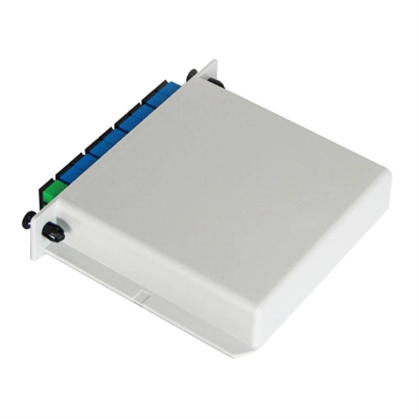
Yes, but the ideal solution is to use a two-way splitter at your ONT. One port is for the phone near the ONT, then use a phone extension cord to "back-feed" to the nearest interior phone jack. Then you can plug a phone into any other phone jack throughout the house and it'll just work. Centralized – A centralized split has one or more splitters together at a centralized location. Centralized splitting occurs often, but not always, in central ofices or. An optical splitter, also known as an optical fiber splitter or fiber optic splitter, is a passive device used to divide an optical signal into multiple outputs. They are primarily used in fiber optic networks to distribute signals from a single source to multiple destinations. This mechanism is. These unassuming devices enable a single optical signal to be divided into multiple paths, making them indispensable for sharing network resources efficiently—from residential FTTH (Fiber-to-the-Home) connections to large-scale telecom backbones. Conversely, it can also combine multiple signals into one. The fiber optic.
[PDF]

This guide will explain their functions, discuss the role of single-mode LC connectors in modern fiber optic systems, and present the logic for their adoption on a broader scale. Proper connection of fiber optic cables is essential to harness these benefits fully, as even minor errors can lead to significant performance issues like signal loss. This article will guide you through the necessary tools, materials, and methods on how to connect fiber optic cables effectively. Fiber optic internet delivers blazing-fast speeds and reliable connectivity, making it a top choice for modern homes and businesses. In this guide, we'll walk you through how to. In this article, we'll explain how to connect multiple Ethernet switches using fiber optic cables and the equipment required for this to work. Network topology refers to the way in which the links and nodes of a network are arranged in relation to each other. There are also fiber-to-fiber versions that translate between different fiber types, wavelengths, or distances. Common families support 10/100/1000 Ethernet and. This is where single-mode fiber optics comes in. Single-mode fiber is being viewed as the backbone of enterprise connections, and it is used to facilitate all 400G solutions and real-time AI solutions/applications, due to its ability to transmit data over long distances with minimal signal loss.
[PDF]
Follow the described steps to factory reset an IBM Brocade switch running FOS 7. Run firmwarecleaninstall on each CP or switch After firmwarecleaninstall, all passwords, such as root, admin, factory and user are cleared (set to the default value). Before installing a new software version and RCF files, you must erase the current switch configuration and perform basic configuration. Log in to the switch as an administrator. The system is halted flushing ide devices: hda Power down. Display information about switches in the fabric. Display how long the switch is running, number of connected users and the system load for the past 1, 5 and 15 minutes. Display or set date and time (This is Readonly if NTP is. This video will demonstrate clear procedure of an interface and ASIC counters on Brocade B-Series Switches and Directors Welcome to Dell Technologies Connectrix Brocade How To Series. WARNING: This is a.
[PDF]

The FC/PC (Physical Contact) and FC/APC (Angled Physical Contact) fiber optic connectors are standardized under TIA EIA/TIA-604-4 and IEC 61754-13. ABSTRACT: This standard describes the point-to-point physical interface portions of Fibre Channel serial electrical and optical link variants that support the higher level Fibre Channel protocols includ-ing FC-FS, HIPPI, IPI, SCSI and others. This standard is recommended for new implementations but. Fiber connector types LC, SC, FC, ST, MTP, and MPO are widely used in past and present. What are the differences between them? Who is the most popular one? Find the answer in the article. What is a Fiber Connector? The optical fiber connector is a kind of detachable passive optical component used. An optical fiber connector is a device used to link optical fibers, facilitating the efficient transmission of light signals. An optical fiber connector enables quicker connection and disconnection than splicing. Unlike fiber splicing, which is permanent, connectors allow for easy connection and disconnection of cables, making them ideal for maintenance and flexibility in. Understanding fiber connector types—SC/APC, SC/PC, LC/UPC, LC/APC, ST/PC, FC/PC, and FC/APC—is essential for selecting the right interface for your application. Each type varies by shape, polish (APC, PC, or UPC), and return loss performance, which affect PC, UPC, and APC Polish Styles: What's the.
[PDF]

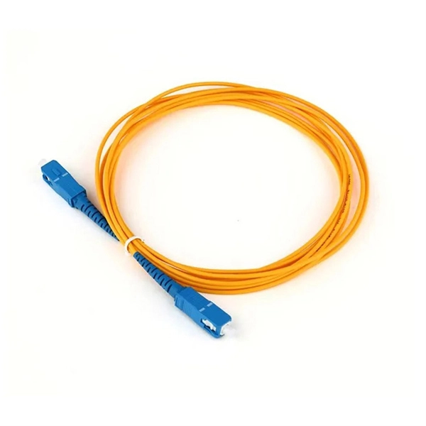
Every fiber optic patch cable has a rated attenuation and bandwidth. For example, OM1 is rated at 200 MHz·km at 850 nm and is intended for use in legacy applications. The higher OM ratings provide more speed and distance. Attenuation should remain within acceptable limits for reliable transmission. Executive Summary: Choosing the right fiber patch cable is one of the most consequential decisions in network infrastructure planning. The wrong choice — whether it's an underperforming multimode grade or an unnecessarily expensive singlemode run — can either cripple your network's reliability or. Fiber optic patch cords are key components for efficient, low-loss optical signal transmission between devices and fiber optic cabling links. One or both ends of the patch cord are equipped with standardized fiber optic connectors, and common interfaces include LC, SC, FC, ST, etc. They are manufactured and tested in compliance with TIA 604 (FOCIS), IEC 61754 and YD/T industry standards. OM1, OM2, OM3, OM4, OM5 or OS2 fiber types are available to meet the demand of. Fiber optic patch cables are ideal for supporting high speed telecommunication network fiber applications. They are lengths of optical fiber terminated with connectors on both ends. Their job is to connect two optical devices, like switches, routers, or optical transceivers that communicate.
[PDF]
Fiber internet provides a higher-capacity connection to your home, which means your Wi-Fi network has more bandwidth to distribute among your devices. This results in faster wireless speeds and a smoother online experience. Although GFiber provides incredibly fast network speeds over wired devices, there are a number of situations to cause your network speeds to slow down. To boost your Internet speed, discover what disrupts or slows your Wi-Fi and wired connections. It acts as a gateway between your local network and the internet, directing traffic between devices and ensuring that data is transmitted efficiently. The type of internet service you have whether it's DSL, cable, fiber-optic, or satellite—can affect speed and reliability. Fiber-optic connections generally offer the fastest speeds and lowest latency. A gig fiber connection will provide around 1,000 Mbps download and 1,000 Mbps upload —but you won't always see those numbers if you run a speed check on your computer. On one hand, a high-quality router can improve network efficiency by optimizing data transmission, reducing congestion, and minimizing errors. On the other hand, a low-performance router or one. Just got Fiber installed, and down speed is phenomenal but I seem to be getting intermittent lag spikes that make things like gaming worse.
[PDF]
An optical module is a typically hot-pluggable optical transceiver used in high-bandwidth data communications applications. Optical modules typically have an electrical interface on the side that connects to the inside of the system and an optical interface on the side that connects to the outside world through a fiber optic cable. The form factor and electrical interface are often specified by an int. Electrical Interface TypesThere have been multiple variants of the electrical interface of optical modules that have been used over the years. The earliest forms of optical modules had an analog electrical interface. In the transmit dir. Many different forms of optical modulation and multiplexing have been employed in optical modules. The most common modulation technique historically has been or NRZ.
[PDF]