
Whether you are a home user, managing a small office, or running a business network, this guide will walk you through connecting your ONT to your router, configuring your network, and optimizing your Wi-Fi for smooth performance. However, setting up a fiber optic connection to your router can seem daunting if you're unfamiliar with the process. In this guide, we'll walk you through how to connect a fiber optic cable to a router safely and efficiently. Why Use Fiber Optic Internet? Before diving into the setup, let's quickly. Setting up a fiber internet connection requires understanding key hardware components and following a specific connection sequence to establish your home network. The fiber. Fiber optic internet delivers lightning-fast speeds, reliable connections, and low latency for streaming, gaming, video calls, and more. Setting up your fiber router correctly ensures you get the most from your connection. This comprehensive guide combines industry standards with field-tested practices to ensure you achieve a rock-solid. In this guide, we'll explain router compatibility, setup steps and whether upgrading your router is necessary to maximize fiber speeds. Here's a simple guide to help you through the process: 1. Check Your Fiber Optic Equipment Before you start, make sure you have the necessary equipment: Fiber Optic Modem (ONT – Optical Network Terminal):.
[PDF]
Explosion proof distribution boxes and electrical enclosures are critical components for ensuring safety in hazardous environments. They are designed to contain internal explosions and prevent ignition of surrounding flammable gases or dust. In this article, we will explore three key aspects:. Explosion-proof enclosures are used by such facilities to ensure the safe housing of electrical components that could cause a spark and ignite these gases in the atmosphere. What Is An Explosion Proof Box or Enclosure? They are a cast aluminum or iron box that can withstand a heavy-duty explosion. Learn what an explosion-proof box is, its types, certifications, applications, and how to choose the right one for safety in explosive environments. They house critical components like circuit breakers, relays, and surge protectors in. The magic of explosion-proof enclosures lies in what you don't see – the physics and engineering principles built into every curve and joint. Manufacturers like Atex Global and Supermec approach design with three non-negotiable principles: These enclosures are built like miniature fortified. An explosion proof enclosure is a specially engineered housing designed to contain internal sparks or explosions and prevent ignition of hazardous gases, vapors, or dust in dangerous environments. Choosing the right one depends on your hazard classification (such as Class 1 Division 2), required.
[PDF]

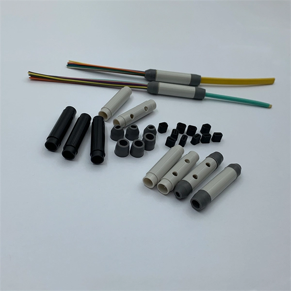
A fiber pigtail is a short optical fiber cable with a connector pre-installed on one end and a bare fiber on the other. It acts as a bridge between optical fibers and devices, making it a vital part of network termination, splicing, and patching processes. In the world of fiber optic communications, reliability and precision are everything. As networks scale to support FTTH rollouts, 5G base stations, and hyperscale data centers, the way fiber is terminated and managed at every endpoint can determine whether a project succeeds or fails. One component. Executive Summary: A fiber optic pigtail is one of the most commonly specified yet least understood components in structured cabling. Get the wrong connector type, the wrong polish, or skip proper fusion splicing technique—and you're looking at elevated signal loss, increased back reflection, and a. ■ What is a fiber optic pigtail cable? A pigtail fiber indicates a short length of optical fiber cable that has a pigtail connector (for example, SC, FC, ST, LC, etc. ) fitted on one end and the other end undressed (for connection through fusion or splicing) to the main fiber optic cable. What does fiber optic pigtail mean? A fiber optic pigtail works like a bridge between two different connection methods. It is usually suitable for field termination using a mechanical or fusion splicer.
[PDF]

Link Aggregation is a generic term for combining multiple network connections to work as one logical connection. It is standardized under the IEEE 802. So, what exactly is an aggregation switch, and how do you choose the right one? Let's examine it in detail. What Is an Aggregation Switch? An aggregation switch is a network device that consolidates traffic from multiple access switches, wireless access points, or other edge devices and forwards it. Is a Aggregation switch just to connect different networks? I have all my Clients wired into the USW Pro this is connected to the UDM by 10g fibre. The NVR is connect via Fibre to the USW as well. So. ? Any hints welcome! Archived post. New comments cannot be posted and votes cannot be cast. The primary function of an aggregation switch is to aggregate and forward data. Link Aggregation, Port Channel, and EtherChannel are related concepts in networking that involve combining multiple physical network links into a single logical link to increase bandwidth, redundancy, and fault tolerance. Let's break them down: 1. A round-robin algorithm is used for load balancing traffic across the interfaces in an aggregated link. Dynamic Link Aggregation (LACP) has been introduced on SonicOS 6. Link. LAG simplifies controller configuration by eliminating the need to configure ports for each interface. If any controller port fails, traffic migrates automatically to other functioning ports. Wireless clients.
[PDF]

The manufacturing process of fiber optic cables involves several crucial steps, including fiber production, cable assembly, testing and quality control, and packaging and distribution. Each step ensures that the cables are produced to the highest standards and can efficiently. The digital revolution continues to drive unprecedented demand for high-speed, reliable data transmission. At the heart of this transformation lies fiber optic cable manufacturing, a precise and sophisticated process that powers our interconnected world. With the global fiber optic market reaching. Fiber optic cables are the backbone of today's high-speed internet, telecommunication systems, and data transfer technologies. Unlike traditional copper cables, fiber optic cables use light signals to transmit data, which allows them to carry large amounts of information at extremely high speeds. The production of optical fiber is a precision-driven process that transforms raw materials like silicon tetrachloride into ultra-thin, high-performance fibers capable of transmitting terabits of data over thousands of kilometers. With the increasing demand for faster and more reliable connectivity, the construction of optical fiber cable factories has become essential. This hair-thin strand of glass or plastic transmits data as pulses of light over long distances with minimal signal loss. The first step in.
[PDF]
A photonic integrated circuit (PIC) or integrated optical circuit is a microchip containing two or more photonic components that form a functioning circuit. This technology detects, generates, transports, and processes light. Photonic integrated circuits use photons (or particles of light) as. architecture and performance of several generations of InP-based PICs. Increased complexity in chip functionality has resulted in a need for increased fabricati n complexity from III-V epitaxy, through wafer fab, die fab, and test. Through continuous learning and improvement, Infinera has. Photonic integrated circuits (PICs) use light (photons) to transmit information, whereas traditional integrated circuits use electricity (electrons), enabling faster signal propagation. Whereas an electronic integrated circuit.
[PDF]

This report lists the top Fusion Splicer companies based on the 2023 & 2024 market share reports. Mordor Intelligence expert advisors conducted extensive research and identified these brands to be the leaders in the Fusion Splicer industry. Fujikura Europe Ltd offers fusion splicers, which are essential for efficiently joining optical fibers. As the official support center for Fitel splicers, OFS. AFL - Fiber optic cable, transmission and substation accessories, outside plant equipment, connectors, fusion splicers, test and inspection equipment. Discover how these fusion-spliced, field-installable connectors simplify installation and improve performance. Are you looking for a professional and reliable fiber optic products manufacturer for your business? Are you still worried about how to find and select a best partner from so many fiber optic products manufacturers? Don't be afraid, Gcabling will help you. In this post, Gcabling, as a professional. Fiber splicing is the process of joining optical fibers to create continuous, low-loss optical pathways used in manufacturing, research, and high-performance fiber systems. In advanced applications, fiber splicing is not a single operation. They are headquartered in locations across the globe, including the United States, China, Brazil, and India, with founding years ranging from 1964 to 2019.
[PDF]
Photovoltaic modules, or solar modules, are devices that gather energy from the sun and convert it into electrical power through the use of semiconductor-based cells. A photovoltaic module contains numerous photovoltaic cells that operate in tandem to produce electricity. A single PV device is known as a cell. An individual PV cell is usually small, typically producing about 1 or 2 watts of power. These cells are made of different. Photovoltaics (PV) is the conversion of light into electricity using semiconducting materials that exhibit the photovoltaic effect, a phenomenon studied in physics, photochemistry, and electrochemistry. Here is a description of their main features and of Enel Green Power's innovative solution. A semiconductor.
[PDF]

Key components typically housed within these boxes include circuit breakers, relays, fuses, and switches, all critical for safe electrical distribution in hazardous environments. Flameproof enclosure (Ex d IIB+H2), which can be used as feed distribution equipment in control and distribution system (such as distribution box, switch box of main circuit, control box, terminal box or motor starting box etc. ) ·Enclosure: stainless steel. Equipped with specialized hinge. Explosion proof equipment is designed to contain internal explosions and prevent ignition of surrounding flammable gases or dust. Rather than stopping an explosion from occurring, the equipment safely manages it within a reinforced structure. They house critical components like circuit breakers, relays, and surge protectors in durable materials such as aluminum or stainless steel. They ensure electrical safety by preventing sparks or heat from igniting flammable substances. As industries evolve, understanding how these devices operate becomes essential for engineers, safety managers, and. Explosion-proof Power Distribution Panel MAMX-02 and MAMX-03 * In-built circuit breaker, AC Contactor, Thermorelay, PLC, Transducer, Soft starter and other components, The panel can install indicator, Pushbutton, Universal switch, Display instrument. * Rated current: 1500A * Steel pipe or Cable.
[PDF]
Flex electrical cable, often referred to as flexible cable or flex, is a type of wire that is designed to withstand repetitive bending and movement without damage. Article 400 covers the general requirements and applications for flexible cords as contained in Table 400. A “flexible cord” is two or more insulated conductors enclosed in a flexible covering. Figure 01 The NEC does not. What is a flexible cable? Flexible cables are cables that have multiple conductors (Class 5 or Class 6 conductors) that form the conductor and are insulated and sheathed in a lightweight, flexible material (usually plastic or rubber). Why choose flexible cables for domestic use? It is suitable for. These include flat flexible cable (FFC), stranded wire, power cables, control cables, and flexible electrical conduit. Each type meets specific needs across industries like automotive, electronics, and medical devices. Here is a quick look at how leading cable types are used worldwide: You can. Power distribution cables present a unique challenge to electrical wire interconnect system engineers. Unlike rigid electrical wiring, which is designed for static installations within buildings, walls, or. In any electrical system—whether powering lights in homes, machinery in factories, or robots in operation—cables are the unsung heroes, safely and reliably transmitting electrical energy. As the backbone of power distribution systems, cables connect power sources (such as circuit breakers) to.
[PDF]

Members of the Cabinet are political appointees and administratively operate their departments. For the current cabinet, see Second cabinet of Donald Trump. The Cabinet of the United States is the principal official advisory body to the president of the United States. The Cabinet generally meets with the president in the Cabinet Room adjacent to the Oval Office in the West Wing of the White. Every President has a lot to do -- especially a modern-day United States President. He or she must: oversee dealing with foreign countries and the defense of our land. keep an eye on how our farms are doing. make sure that. The purpose of the Cabinet is to advise the President on matters relating to the duties of their respective offices. The Constitution does not directly mention a "Cabinet," but. cabinet, in political systems, a body of advisers to a head of state who also serve as the heads of government departments. The cabinet has become an important element of government wherever legislative powers have been vested in a parliament, but its form differs markedly in various countries, the. The Presidential Cabinet acts as a set of advisors for the president. What Is the US Cabinet? The US Cabinet is a series of departments within the.
[PDF]

The voltage in Turkmenistan is 230 volts and the frequency is 50 Hz. Turkmenistan has standardized on type C and type F sockets and plugs. Type E plugs can also be used thanks to their compatibility with type F sockets. If your device plugs don't match Turkmenistan's standards, we recommend purchasing suitable travel adapters in advance to ensure proper use. What power plug types are used in Turkmenistan? Plug type B. Ok, you are going to Turkmenistan, you will use power plugs/outlets similar to the following picture (s): (includes Ashgabat, Mary, Turkmenabat, Dashogus, Konye-Urgench, Turkmenbashi. (more details after you choose where. Everything you need to know about Turkmenistan power outlets, plugs for Turkmenistan, power adapters, voltage, and frequency when travelling to Turkmenistan. Planning a trip to Turkmenistan and wondering if you need a power adapter? Look no further! We've got you covered with this comprehensive. Turkmenistan uses power outlets and plugs of types C & F. Take a look at the pictures below to see what these plugs and power sockets look like: Doesn't look familiar? Do the outlets look different in your country? You'll need a power plug adapter. 220 V has an advantage over lower voltage such as the 110 V that it is cheaper to transmit. On the other hand, 220 V is more dangerous than lower voltages.
[PDF]

Managing optical attenuation helps keep your signal safe. Clean your optical connectors so you do not lose. Optical Signal Attenuation is the single greatest factor limiting the distance and performance of your network. Understanding it is crucial for anyone involved in data centers, telecommunications, or enterprise networking. This guide will demystify signal loss, explore its causes, and show you how. In high-speed environments, where the optical link budget is measured in fractions of a decibel, diagnosing and eliminating unexpected loss is the network engineer's most critical task. This field guide provides a systematic, step-by-step approach to troubleshooting and resolving the most common. Signal loss in Fiber Optic networks can make data slow. It can also break your connection. You should fix it fast to get speed and stability back. > You can solve this with simple steps. Signal Degradation (Loss of Light) When the signal quality degrades, it could be a sign of attenuation or excessive loss in the system. The signal might become weaker, resulting in slower speeds or dropped connections. -. Fiber optic networks are celebrated for their speed and reliability, but even the best systems can encounter problems. When issues like signal loss, slow speeds, or intermittent connectivity arise, systematic troubleshooting is key. Things like impurities in the fiber core and reflections at the core-cladding edge cause this drop.
[PDF]

