An optical fiber is a cylindrical ( waveguide) that transmits light along its axis through the process of total internal reflection. The fiber consists of a core surrounded by a layer, both of which are made of materials. To confine the optical signal in the core, the of the core must be greater than that of the cladding. The boundary between the core and cladding m.
[PDF]

This paper will review the development of fiber-optic high-temperature sensors over the last 30 years, presenting their design and fabrication methods according to sensing type and typical temperature measurement performance. The full paper consists of eight sections. Fiber-optic high-temperature sensors are gradually replacing traditional electronic sensors due to their small size, resistance to electromagnetic interference, remote detection, multiplexing, and distributed measurement advantages. This paper reviews the sensing principle, structural design, and. Luna's Optical Backscatter Reflectometer (OBR) products are based on OFDR and provide a level of detail and precision not available with the prevailing fiber optic diagnostic tool - the optical time domain reflectometer (OTDR). OBR systems map out loss along a single-mode fiber (SMF) or multi-mode. breadth and most comprehensive solutions for optical communications test products to be found in one place. Corning's High Temperature Fibers are designed for applications requiring improved fatigue resistance, high usable strength, and excellent resistance to higher temperatures and hydrogen permeation. Thus, wireless communication -situ processing of data would combined with in significantly improve the ability to include sensors into high temperature systems and thus lead toward more intelligent engine systems. NASA Glenn Research Center (GRC) is presently lea, communication systems,ding the.
[PDF]

The document discusses optical detectors used in fiber optic communications systems. It describes the functioning of PIN photodetectors and avalanche photodetectors (APDs). Their performance. An optital detector is a device that converts light signals into electrical signals, which can then be amplified and processed. Such detectors are one of the most important components of an optical fiber communcation system and dictate the performance of a fiber optic communication link. PIN Photodiode A PIN photodiode is a widely. Detectors perform the opposite function of light emitters. The most common detector is the semiconductor photodiode, which produces current in response to. It explains how these devices use optical fibers to measure quantities like temperature, mechanical strain, pressure, and vibrations by detecting changes in light propagating through the fiber. A central focus is on sensors based on fiber Bragg gratings, where the Bragg wavelength is sensitive to. Optical Power Meters: These devices measure the power of optical signals in fiber optic cables. This information helps in maintaining signal integrity and quality across the.
[PDF]

An optical module sends data as light through fiber cables. Light is faster than electricity, making it great for quick communication. The optical module serves as a crucial component in optical fiber communication systems, operating at the physical layer, which is the lowest layer in the OSI model. Its primary function is to achieve optoelectronic conversion by converting electrical signals into optical signals and vice versa. This technology is crucial for fast and reliable data transfer in networks. Optical modules typically have an electrical interface on the side that connects to the inside of the system and an optical interface on the side that connects to the outside. Optical fiber transmission forms the backbone of modern high-speed communication networks, enabling the efficient transfer of massive datasets across vast distances. These modules typically consist of a transmitter, which converts electrical signals into a light signal, and a receiver, which converts the received signal back. In high-speed data networks, the seamless integration of fiber optic cables with SFP (Small Form-Factor Pluggable) modules is critical for reliable signal transmission. SFP transceivers bridge electrical and optical signals, making them indispensable in data centers, telecom networks, and.
[PDF]

When it comes to testing fiber optic cables, a Visual Fault Locator (VFL) is an essential tool in your toolkit. A VFL is used to detect faults, breaks, or bends in fiber optic cables by emitting a bright red light that is visible even through the fiber's jacket. Let's dive into everything you need to know about mastering VFLs. In the. Finding a break in a fiber optic cable can be challenging but is essential for maintaining a stable network. Common Indicators of a Cable Break Signal. Here Kingfisher's experienced engineers share their experience in best practices and procedures for fiber optic testing related mostly to installation and maintenance. We hope that by sharing our knowledge, we will help grow our industry. Please enjoy & pass on these notes. The following are key methods and techniques used for optical fiber cable line failure positioning: Visual Inspection: Perform a visual inspection of the. Locating faults in fiber optic cables requires specialized tools and techniques. Look for dirt, scratches, or damage on the connectors. Clean. To ensure the quality and continuity of fiber optic services, it is essential to identify and locate fiber optic cable faults as quickly and accurately as possible. In this article, you will learn about some of the common methods and tools for fiber optic testing and troubleshooting.
[PDF]

This article will give you an overview of the use cases for fiber-optic networking, some of the terms used in fiber networking, and suggestions for setting up a fiber network. Once you understand the basic concepts, you can check out my Recommended Equipment section toward. Fiber tapping is a network tap method that extracts signal from an optical fiber without breaking the connection. Tapping of optical fiber entails diverting some of the signal being transmitted in the core of the fiber into another fiber or a detector. Fiber to the home (FTTH) systems use beam. Optical fiber is a technology used to transmit data by sending short light pulses along a long fiber, which is typically made of glass or plastic. In optical fiber communication, metal wires are preferred for transmission because the signals travel more safely. Optical fibers are also resistant to. Photo: Light pipe: fiber optics means sending light beams down thin strands of plastic or glass by making them bounce repeatedly off the walls. This is a simulated image. Note that in some countries, including the UK, fiber optics is spelled "fibre optics. " If you're looking for information online. This manual covers everything about fiber optic cables, how they work, where they are used, and what is new in this area of technology. The choice of fiber optic cable depends on the specific needs of the application, as well as the.
[PDF]

Huawei's fiber to the room (FTTR) solution extends fibers to rooms and provides various gigabit Wi-Fi 6 master/slave FTTR units, all-optical components, and optical cable routing tools. This enables home users to enjoy stable gigabit Wi-Fi experience from anywhere in the home. FTTR is generally an extended FTTH (Fiber To The Home) solution. Drop optical cable terminates at ATB (Access Terminal Box). A patch cord of 1 or 2 m. Huawei will soon be selling its "FTTR" system for do-it-yourself fiber optic home cabling in Germany. Huawei FTTR: Bonding tool for fiber optic installation. A special glue. Fibeye provides FTTR(Fiber to the room) solutions, We specialize in Huawei-adapted FTTR solutions that can help you tap into new markets and grow your business. What is FTTR FTTR(Fiber-to-the-room), is an innovative solution that allows telecom operators to bring optical fibers directly into. Guess what, I spotted Huawei's transparent fibre optic offering! The best Wi-Fi is wired Last year, I wrote about Singtel's FibreEverywhere offering, which allows homeowners to install high-speed wired cabling in every room - without any drilling or trunking. Poor Wi-Fi coverage at home is a common. Watch the video to discover how to use the Huawei FTTR fiber installation kit to route transparent optical cables.
[PDF]

Identify and compare relevant B2B manufacturers, suppliers and retailers. Identify and compare relevant B2B manufacturers, suppliers and retailers. Identify and compare relevant B2B manufacturers, suppliers and retailers Max. Brolis Sensor Technology specializes in advanced photonic sensor technologies, including the development of integrated optical sensors for healthcare and industrial applications. Their innovative sensors utilize. Fiber Optic Devices Ltd. (FOD), an employee owned company, is a complete fiber optic technology company offering a variety of products and services to the OEM and End-user markets. Founded in 1991, FOD is a recognized leader in partnerships in the design and manufacturing of Fiber Optic Components. Also, please take a look at the list of 38 optical sensor manufacturers and their company rankings. Here are the top-ranked optical sensor companies as of May, 2026: 1. WIN SOURCE ELECTRONICS, 2. Vishay Intertechnology, Inc. The Workshop of Photonics (WOP) specializes in femtosecond laser micromachining, providing ultra-high precision services for various materials, including glass and ceramics. Their innovative approach enhances productivity and provides critical data for improving nutrition and.
[PDF]

Optical couplers can split or join signals in fibers. You can connect many users to one port with 1:n or 2:n splitters. These devices work both ways, which helps strong network communication. They help send. This small device connects or joins optical fibers together. It helps networks grow and change when needed. Learn about the two main types of fiber optic couplers: fused and planar. Fused. How to Choose the Right Fiber Coupler (FTTH, Data Center & More) Are you in the process of designing a Fiber to the Home (FTTH) network, but wondering how to split one fiber for multiple users? Or maybe you are operating a data center, and you would like to use a single signal to provide to. Fiber optic couplers are optical devices that connect three or more fiber ends, dividing one input between two or more outputs, or combining two or more inputs into one output. The device allows the transmission of light waves through multiple paths. Fiber optic couplers can either be passive or. A fiber optic coupler is a passive optical component that splits, combines, taps, or redistributes light between optical fibers. In real-world networks, couplers let one signal reach many users, allow several signals to share one fiber path, or sample a small amount of light for monitoring. 5/125 µm fiber, with low insertion loss and a broad operating wavelength range from 800 to 1600 nm. The 1x2 and 2x2.
[PDF]
We describe a theoretical and experimental study of an intensity-based, dual-wavelength referenced fiber optic temperature sensor utilizing temperature-induced spectral shifts of optical thin-film interference coatings, deposited on a sensor fiber end. We present coating design considerations that. This study proposes the development of a dual-wavelength optical fiber sensor (DWOFS) that integrates two optical fiber structures in a multimode transmission line to measure the refractive index and temperature of a liquid concurrently. One structure is based on a refractive index sensor that. ter. The dual-wavelength fiber laser has a ring cavity composed of two FBGs with central wavelengths of 1550. Through monitoring the wavelength shift and the output power difference of the dual-wavelength fiber laser, the simultaneous measurement for RI and temperature is. To improve the sensitivity measurement of temperature sensors, a fiber optic temperature sensor structure based on the harmonic Vernier effect with two parallel fiber Sagnac interferometers (FSIs) is designed, and theoretical analysis and experimental testing are conducted. The FSI consisting of. Fiber-optic high-temperature sensors are gradually replacing traditional electronic sensors due to their small size, resistance to electromagnetic interference, remote detection, multiplexing, and distributed measurement advantages. This paper reviews the sensing principle, structural design, and.
[PDF]
A simple rule is that each device needs two cores—one for sending and one for receiving data. Start by counting how many devices you're connecting. For example, if you have 10 devices, you'll need at least 20 cores. The total number of cores for a 1pc fiber patch cable is calculated as the number of branches multiplied by the number of cores per branch (if there are no branches, the number of branches = 1). For example, the total number of cores in an MTP®-8 trunk cable equals 4 (number of branches) x 8 (MTP-8. The number of optical cores in an optical fiber is the total number of equipment interfaces multiplied by 2, plus 10% to 20% of the spare quantity, and if the communication mode of the equipment has serial communication and equipment multiplexing, you can reduce the number of cores. The number of. One key factor is the number of cores, which impacts how much data you can transmit. This post will guide you through understanding fiber optic cores and selecting the perfect cable for your needs. Understanding Fiber Cores: Core: The central glass fiber that transmits light signals. For example, an MTP®-8 trunk cable with four branches and eight. Tip: Round counts to the connector pack before you buy. Tip: Keep one spare block for moves, adds, and changes. To calculate teh total number of fiber strands that will be.
[PDF]

Scattering accounts for the greatest amount of attenuation in a fiber cable, between 95 and 97 percent. Light traveling through the fiber interacts with the densities as shown in the light and is then partially scattered in all directions. Fiber optic cables have many advantages, but one of the downsides just like with copper cable, is that it can experience what is called attenuation. Attenuation refers to the loss of light as it travels down the fiber. This can be due to a variety of factors: scattering and absorption, intrinsic. This attenuation is inevitable, so the smaller the attenuation value, the longer the transmission distance of the same optical power. The better the quality of this fiber patch cable. It indicates the amount of signal reflected back. At TREND Networks, we are frequently asked how much loss is allowed when conducting testing on fiber optic cabling. Unfortunately, it is not a simple answer and depends on several factors. So how do you determine acceptable loss? When testing fiber optic cabling, determining acceptable loss is. Understanding fiber loss is vital in maintaining a reliable, efficient network. Understanding it is crucial for anyone involved in data centers, telecommunications, or enterprise networking. Here are the details and instructions about each field and how they contribute to the calculation: 1. Attenuation Coefficient (dB/km): This value represents the inherent signal loss per kilometer of.
[PDF]

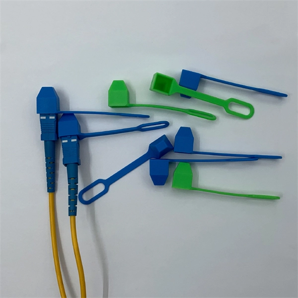
This article will compare waterproof connectors and non-waterproof connectors, highlighting their key differences, advantages, and best use cases in FTTH deployments. 🔍 What Are Waterproof Connectors?. In modern fiber optic deployments, one of the biggest challenges is ensuring stable and long-term connectivity in harsh outdoor environments. The comparison is typically triggered during outdoor deployments, edge network extensions, or hybrid indoor–outdoor transitions where connectors may be exposed. This is where Ruggedized Fiber Optic Connectors come in. Whether you are connecting a Remote Radio Unit (RRU) for Ericsson, Nokia, or Huawei, or setting up a harsh-environment sensing network, choosing the right waterproof interface is critical to preventing signal loss and network downtime. In. In today's fast-paced digital world, the choice of fiber optic connectors can significantly impact performance, reliability, and longevity of networking solutions. Among the varieties available on the market, waterproof fiber optic connectors have emerged as a superior option for many applications. In this blog, we will focus on comparing the performance of Mini LC.
[PDF]
