A fiber media converter takes an Ethernet signal on copper (RJ-45) and converts it to an optical signal on fiber, or vice versa. There are also fiber-to-fiber versions that translate between different fiber types, wavelengths, or distances. Full range of Fiber Optic Modems to convert Serial Data, T1, E1, T3, E3 and Phones for fiber communication. Featuring high and low speeds and field-changeable interfaces. Applications include satellite downlinks, DSUs, various Crypto devices, Channel Banks, SCADA and Process Control Networks. In this article, we'll explore the seamless transition from T1 and E1 lines to fiber optics, enabling you to enjoy lightning-fast connectivity. E1 and T1 leased lines are digital technologies that connect two locations with a private, dedicated connection. They offer dependable and secure data. A fiber optic network is a way to transmit data and realize communications via fiber optic cabling instead of Ethernet cabling. A fiber optic network, in other words, utilizes another media to conduct data transmission between the main and edge network devices. Copper Ethernet Cabling VS. These devices are essential when you need to bridge fiber optic cables with Ethernet cables, especially in long-distance or high-speed network setups. There are no specific requirements for this document. The information in this document is based on all Catalyst 9000 Series switches. This includes Doppler.
[PDF]

The SC pigtail is not properly plugged into the slot of the fiber media converters or has been disconnected. Check whether the fiber optic line is broken. erconnect (DCI) networks. The 6500 RLS is an open and programmable photonic networking platform that is simple to deploy and operate, and optimized for space-constrained, sive capacity scalability. Compact, modular transport devices have emerged to solve footprint challenges in networks requiring massive capacity. Ciena's WaveLogic 6 Extreme 1. 6T quantum-safe encryption solution on the Waveserver platform was designed with this in mind, supporting QKD system interworking and NIST-certified PQC algorithms. Check whether the fiber interfaces are. Fiber optic troubleshooting is an essential skill for network administrators, technicians, and engineers responsible for maintaining and repairing fiber optic systems. These high-speed, high-capacity communication networks are increasingly replacing copper cables, offering superior performance and. Problems within a fiber link can occur due to a wide variety of reasons. A very common problem is that a connector is not fully engaged - often hard to notice in a crowded patch panel. Or it could be caused by the quality of the connector itself, such as poor end-face geometry that doesn't pass the.
[PDF]
Comprehensive guide to underground fiber optic cable types, installation, pricing, conduit systems, standards, and armored solutions for projects. Underground fiber optic cable is designed for direct burial or conduit installation and is widely used in FTTH networks, backbone infrastructure, and. Installing fiber optic cables underground involves far more than digging trenches and placing cables. It forms a critical backbone for modern communication networks across both urban and rural environments. Project success depends on careful planning, precise installation practices, and proper. Installing underground fiber optic cables is critical to establishing high speed internet infrastructure that delivers reliable connectivity for businesses nationwide. 02 Methods used for placing fiber optic cables in ducts are essentially the same as.
[PDF]

The primary problem encountered is signal loss, also known as attenuation. Attenuation can be due to absorption, scattering, or bending losses, affecting the quality and speed of data transmission. Attenuation in fiber optic cables is the reduction in signal strength during. To be able to judge whether a fiber optic cable plant is good, one does a insertion loss test with a light source and power meter and compares that to an estimate of what is a reasonable loss for that cable plant. The estimate, called a "loss budget" is calculated using typical component losses for. F iber optic networks rely on the efficient transmission of light signals to deliver high-speed data over long distances. However, various factors can cause signal degradation, leading to performance issues and reduced network reliability. Fiber optic signal loss, also known as attenuation, occurs. A significant signal loss in the optical fiber can cause unreliable transmission. How can we know the value of losses on the fiber link? Read on, this post will teach you how to calculate the losses in optical fiber and judge the fiber link performance. The uses various types of network cables, including multimode and single-mode fiber-optic cable. It can also break your connection. High attenuation makes your system not work well. You should fix it fast to get speed and stability back. > You can solve this with simple steps.
[PDF]

Home and business fiber optics projects typically range from a few hundred to several thousand dollars, depending on run length, fiber type, and labor needs. The main cost drivers are materials, installation time, and environmental factors that affect trenching, conduit, and terminations. Commercial building installations with 100-200 network drops generally range from $15,000 to $30,000. Single-mode fiber costs less per foot than multimode fiber, but it requires more. What is Fiber optic network design? Fiber optic network design involves the planning, routing, and drafting of Fiber cable layouts to support high-speed data transmission. It includes detailed mapping of backbone, distribution, and drop connections for FTTH, FTTP, FTTx, and enterprise networks. Fiber optic network design refers to the specialized processes leading to a successful installation and operation of a fiber optic network. It includes first determining the type of communication system (s) which will be carried over the network, the geographic layout (premises, campus, outside. According to ResearchAndMarkets, the global market for fiber optics was estimated at $5. 8 billion in 2022 and is expected to reach $11. This is the dominant broadband access technology across half of OECD countries today. The price landscape varies from basic drop cables to enterprise backbone runs, with per foot and per reel pricing common in estimates. This guide presents cost ranges.
[PDF]

Power cycling or restarting your ONT (Optical Network Terminal) often resolves simple troubleshooting internet issues. Use the table below to see expert-recommended first steps for fiber troubleshooting. Fiber optic networks are celebrated for their speed and reliability, but even the best systems can encounter problems. This guide will walk you through diagnosing and resolving common. Is your Brightspeed fiber internet not working? These steps can help resolve common fiber internet problems. In many cases, a fiber connection problem originates from one of the following. When your fiber optic network stops working, begin with a structured approach. First, check the basics—look for power issues on your optical network terminal and inspect all cables for visible damage. Many fiber internet problems come from dirty connectors or loose plugs, not major faults. These high-speed, high-capacity communication networks are increasingly replacing copper cables, offering superior performance and. Switch A is on the router end, devices connected to this switch get DHCP leases and can browse the internet without issue. Sign in to get your Wi-Fi details, check service status, test equipment speed, and more. Find your appointment using your order ID or internet account number. Check your bill, set up.
[PDF]
A fiber optic switch allows optical signals to be selectively switched from one fiber to another, while a fiber optic splitter divides an optical signal into multiple signals, allowing it to be transmitted to multiple devices. It is essentially a switch that operates at the optical layer of a network, rather than at the electrical layer. Conversely, it can also combine multiple signals into one. Its primary role is in Passive Optical Networks (PON), which are the foundation of. A fiber optic splitter is a passive optical component that divides a single incoming optical signal into two or more outgoing signals, or combines multiple incoming signals into one. The optical network system uses an optical signal coupled to the branch distribution. The fiber optic. While the splitter doesn't manage or direct traffic like a switch, it does allow multiple devices to access the same network connection. The devices connected to the splitter typically need to be configured to work with the shared connection, and bandwidth may be divided among the devices based on. A passive device used to split or combine signals on fiber optics may be called a splitter, combiner or coupler, but splitter is the most common term. They have been used since the 1980s to create networks and provide the technology for today's passive optical networks used in fiber to the home.
[PDF]

The short answer is no - RJ45 connectors are designed for electrical Ethernet signals, while fiber optics transmit light pulses through glass or plastic. However, modern networks often combine both technologies. Traditionally, network switches have been connected using copper cables, but with the increasing demand for high-speed and reliable connectivity, fiber optic cables have gained prominence. If you plan to upgrade to fiber optic network or blend fiber optics into your existing legacy network, you will require a fiber optic. Fiber optic cables are often seen as the gold standard for network cabling. Unlike copper wires, which are limited by lower data transmission speeds, shorter transmission distances, and higher susceptibility to electromagnetic interference, fiber optic cables offer unparalleled performance and can. Briefly, an ONT is a modem that uses optical fiber cables that bridge the internet connection from an ISP (internet service provider) to the end user of fiber internet, while Ethernet cables are used to connect the ONT device to your router that provides internet in your home and offices. Other than entry level network switches, most of today's network switches include one or more GiBC (Gigabit Converter) or SFP (Small Form-factor Pluggable) slots. SFP modules insert into these slots and and require two strands of fiber, typically duplex Using multi mode fiber (for runs under 1000.
[PDF]

One SFP module is inserted into the switch's SFP port, and another module is inserted into the SFP port of the target device, facilitating data transmission through the fiber optic cable. SFP ports are small hot-pluggable module interfaces typically used for connecting fiber optics or copper cables. They support various transmission rates and distances, including 1G, 10G, and higher speeds. SFP modules can be selected based on the requirements, whether it's single-mode fiber for. An SFP port is a physically small slot in a networking device that accepts an SFP module insert. Most modern networking devices, such as Ethernet switches, servers, routers, network interface cards, and fiber media converters, generally have two or more built-in SFP ports. You may connect different. In plain terms, an SFP port on a gigabit switch is the little plug-in hole that gives the switch physical flexibility — the ability to use fiber one minute and copper the next without buying a different switch. Unlike fixed RJ45 copper ports, SFP ports support both fiber and copper modules, enabling far longer distances, greater flexibility, and improved scalability in enterprise. First, to connect SFP modules with fiber optic cables, ensure that the module type matches the line, as there are different modules for single-mode and multimode fiber. Next, insert the module firmly and securely into the SFP port, then attach the cable to the module using the connector. Switches with SFP ports can.
[PDF]

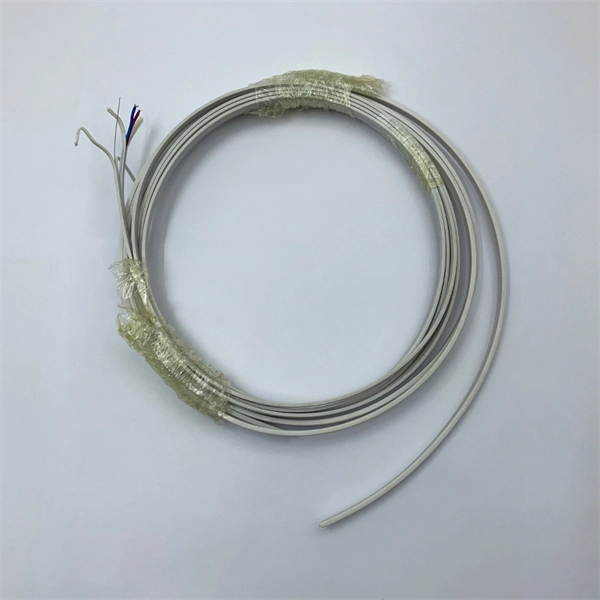
How to Install a Fibre Connector into a Patch Panel (Easy fibre optic connector installation) How to Install a Fibre Connector into a Fibre Optic Patch Panel. How do you install fibre optic connectors?. Connecting a fiber patch panel to a switch is a critical step in setting up a fiber optic network. There are different types of connectors. In today's high-performance networks, fiber optic patch cables are the lifelines that ensure smooth data flow across switches, servers, and routers. Even the most advanced optical transceivers can only perform at their peak when paired with properly installed, clean, and precisely managed fiber. Choose an SFP module based on the fiber optic cabling that will be connected to the network switches. SFP transceiver modules almost always require two fiber optic cable strands. A Fiber Patch cord connects two devices. You plug it into a switch, router, or patch panel. It's ready to use out of the box. A pigtail is for splicing. You fuse it to a. With a railroad switch (patch panel), the train (data) can travel from A to B, C and even more destinations, otherwise it can only go from A to B, or C to D. This article, What Is a Patch Panel Used for?, has explained it thoroughly.
[PDF]

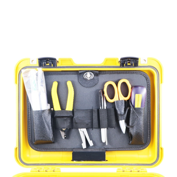
6 core Fiber Optical Splicing With 24 Port LIU || Full Installation || Beginner Watch this video Fiber optic splicing is the process of joining two fiber optic cables together to create a conti. more. In this article, we'll explain how to connect multiple Ethernet switches using fiber optic cables and the equipment required for this to work. Network topology refers to the way in which the links and nodes of a network are arranged in relation to each other. Simply put, it defines how network. Choose an SFP module based on the fiber optic cabling that will be connected to the network switches. SFP transceiver modules almost always require two fiber optic cable strands. Most modern SFP transceiver modules. Most modern fiber-enabled network switches require an SFP transceiver module featuring a duplex (two strand) multimode OM3 or duplex single mode OS2 connection with LC connectors. Direct attach cables with pre-terminated SFP connections may also be used. Download the Application PDF SFP transceiver. This article will guide you through the necessary tools, materials, and methods on how to connect fiber optic cables effectively, ensuring you achieve optimal performance from your fiber optic network. These diagrams help engineers plan infrastructure for residential and commercial buildings. By using light signals, fiber optics provide faster speeds and better reliability than.
[PDF]

Fiber optic patch cable are used to transmit optical signals between two devices or subsystems. They work by using the principle of total internal reflection, which occurs when light travels through a material with different refractive indices. They act as the critical link for interconnecting devices like optical switches, servers, and distribution frames. Understanding the various technical. A fiber optic patch cable is a short piece of fiber with connectors on both sides. It connects one device to another, often within the same rack or across neighboring network equipment. These cables carry data in pulses of light. There are mainly two types of fiber optic patch cables: single-mode. As networks move to higher speeds and higher density, choosing the right fiber optic patch cords becomes critical to the reliability of your system. It is designed for flexible, short-distance connections within networks. They are also called fiber jumpers. It consists of two fiber connectors on each end and a fiber.
[PDF]
Choose an SFP module based on the fiber optic cabling that will be connected to the network switches. In addition, fiber cables can transmit data over several kilometers without signal degradation, making them ideal for connecting switches in large campus networks and between different buildings. As they do not emit electromagnetic signals, they're difficult to tap and secure against eavesdropping. Most modern SFP transceiver modules. Hi Experts, I have a basic knowledge of network and need some help. I need to connect 4 Floor Building with 4 Cisco 2960 - 48 ports switch each other and it needs to be through a fiber. So all PCs connected to each switch would reach the LAN/WAN from the other switch. (attached is the image here. Fiber optic cabling is increasingly used to connect network switches and other datacom equipment, especially in long-distance and mission-critical applications. Fiber provides: Increased internet signal bandwidth. Another way is to put a switch at Location B and interconnect using SFP modules. But is it possible to connect AB and BC cables using fiber optic patch cords ? Will it work in this fashion ? If this can work, I. We can use either the cat6 cable or fiber optical cable to link two network switch. One of the advantages of fiber optical cable is its fast speed. In this video, you will see how to link two network ports together to achieve 2G bandwidth between the switches. You even can connect more.
[PDF]
