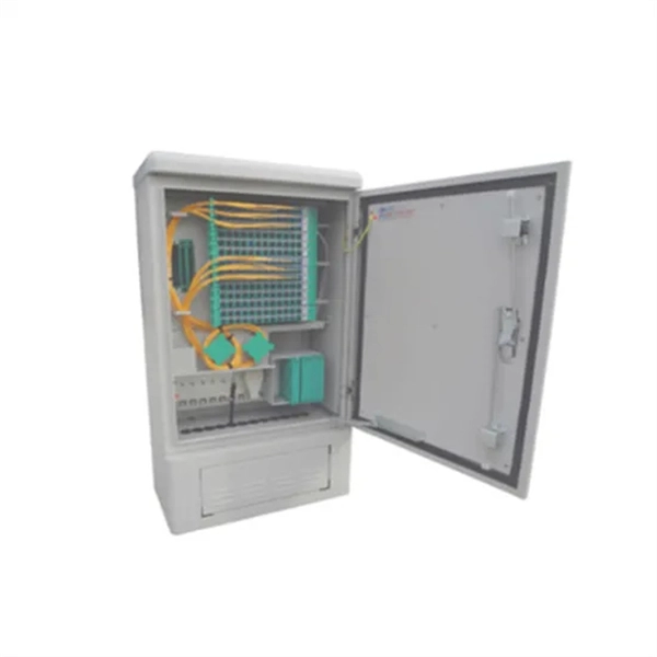
A distribution box, also known as a fiber distribution hub or optical distribution box, is a larger enclosure designed to manage and distribute fiber optic cables to multiple endpoints. It serves as a central point for connecting and organizing numerous fiber optic. Although all three are related to fiber connection and management, their installation locations, functional roles, and positions within the network architecture are fundamentally different. Confusing these devices may lead to non-standard cabling at best, and serious challenges in network. In modern FTTH (Fiber to the Home) and optical communication networks, three types of fiber distribution products are widely used: Splitter Distribution Box, ODF (Optical Distribution Frame), and Fiber Terminal Box. The functions of the four connectors can be. First, let us learn the common point among ODF, fibre optic termination box and fiber optical distribution box, actually, they have similar function, we sort out them as following 4 aspects: 1. fiber termination and optical signal splitting 4. What is the difference between these fiber boxes.
[PDF]

TendersOnTime, the best online tenders portal, provides latest Namibia Optical Fibre tenders, RFP, Bids and eprocurement notices from various states and counties in Namibia. Thank you for visiting Swanib Namibia! To find the solution for your electrical needs, visit our Products or Services page. Swanib Cables, a distributor of electric cables, transformers and fibre optic cables to the Namibian mining, utilities / infrastructure and telecom sectors has been a market. Within the team, a combined 31 years' experience in Construction, Civils, and Fibre Optics. com offers an unmatched database of Optical Fibre Cables tenders from Namibia, more than any other platform. Daily, new procurement. Use this hollow-core fibers buying guide to compare major types, define selection criteria, and find suppliers: Professional purchasing of high-value photonics products is a substantial responsibility, where a structured decision-making process is essential. RP Photonics offers a lot of help: Get. Oryx Fibre Infrastructure is an open access fibre optic network provider in Namibia that owns and operates long distance (backhaul and long haul) fibre infrastructure. We own our secure transmission and backbone fibre infrastructure and provide connectivity services to telecommunications operators.
[PDF]
G657A2 bending insensitive singlemode fiber combines two attractive features: excellent low macro-bending sensitivity and low water-peak level. It is comprehensively optimized for use in O-E-S-C-L band (1260 -1625 nm). FOSC ® 450 B6 Fiber Optic Splice Closure, Gel Cable sealing, no pre-installed tray, 6 cable attach., three ground feedthrough lugs, with test valve, Build America Buy America (BABA) Finish making your selections or clear them to view relevant specifications. B2 Including the IEC 60793-2-50 type Bl. b2 Optical Fiber Specification. Use the code in the “Fiber Type” column to replace the XX notation in the catalog number shown on the catalog page. This identifies the fiber that will be provided with the cable choice. The fibers in all completed cables are tested 100% at the factory for attenuation, and each fiber must meet the. trip force (Force to mechanically strip the and ≤ 5. low water-peak level. It is comprehensively optimized for use in O-E-S-C-L band. Outdoor dry core optical fiber Multi Loose Tube cable with glass yarns as strength member, Corrugated Steel Tape (Full Rodent Protected) armor and polyethylene outer jacket. Product feature: This cable has improved rodent protection by Corrugated Steel Tape (Full Rodent Protected). Existing out of.
[PDF]

An optical module sends data as light through fiber cables. Light is faster than electricity, making it great for quick communication. The optical module serves as a crucial component in optical fiber communication systems, operating at the physical layer, which is the lowest layer in the OSI model. Its primary function is to achieve optoelectronic conversion by converting electrical signals into optical signals and vice versa. This technology is crucial for fast and reliable data transfer in networks. Optical modules typically have an electrical interface on the side that connects to the inside of the system and an optical interface on the side that connects to the outside. Optical fiber transmission forms the backbone of modern high-speed communication networks, enabling the efficient transfer of massive datasets across vast distances. These modules typically consist of a transmitter, which converts electrical signals into a light signal, and a receiver, which converts the received signal back. In high-speed data networks, the seamless integration of fiber optic cables with SFP (Small Form-Factor Pluggable) modules is critical for reliable signal transmission. SFP transceivers bridge electrical and optical signals, making them indispensable in data centers, telecom networks, and.
[PDF]

When it comes to testing fiber optic cables, a Visual Fault Locator (VFL) is an essential tool in your toolkit. A VFL is used to detect faults, breaks, or bends in fiber optic cables by emitting a bright red light that is visible even through the fiber's jacket. Let's dive into everything you need to know about mastering VFLs. In the. Finding a break in a fiber optic cable can be challenging but is essential for maintaining a stable network. Common Indicators of a Cable Break Signal. Here Kingfisher's experienced engineers share their experience in best practices and procedures for fiber optic testing related mostly to installation and maintenance. We hope that by sharing our knowledge, we will help grow our industry. Please enjoy & pass on these notes. The following are key methods and techniques used for optical fiber cable line failure positioning: Visual Inspection: Perform a visual inspection of the. Locating faults in fiber optic cables requires specialized tools and techniques. Look for dirt, scratches, or damage on the connectors. Clean. To ensure the quality and continuity of fiber optic services, it is essential to identify and locate fiber optic cable faults as quickly and accurately as possible. In this article, you will learn about some of the common methods and tools for fiber optic testing and troubleshooting.
[PDF]

IEC fiber connector standards establish the global specifications for connector geometry, mating interfaces, optical performance classes, and mechanical testing across all fiber network environments. Optical connectors are used to connect optical devices to other optical devices or systems. However, each connection introduces a certain amount of insertion and return loss that. Connectors play an important role in Enterprise network architecture. They give you the power to add, drop, move, and change the network. is a small cylinder used to mount. The Fischer FiberOptic Series offers robust and faultless optical performances in any conditions. Combined with easy use, cleaning and maintenance. Tested for harsh and extreme environments (Norm IEC 61753-1 Cat. These standards ensure that passive fiber-optic components remain interoperable, stable, and. designed for diverse fiber optic applications. But what exactly sets a fibe optic connector apart in terms of its merits? The primary purpose of a fiber optic connector is to terminate the ends of fiber optic cables, ensuring they can be int rconnected reliably with minimal optical loss. After. Fiber optic technology is used in ever-increasing applications due to its inherent advantages (lower weight, EMI/RFI immunity, higher bandwidths and distances) over copper. There are many.
[PDF]
They function as junction points that manage, protect, terminate, and distribute fiber optic cables, ensuring efficient data transmission between different network elements. Fiber Distribution Boxes (FDBs) are critical components in modern telecommunications infrastructure, particularly in fiber optic networks. Whether you're a network technician, IT professional, or simply looking to understand fiber optic networks. A fiber distribution box (FDB) is a passive enclosure that provides secure splicing, termination, and distribution of optical fibers. It typically contains splice trays, adapters, and cable routing components to manage fiber connections. FDBs are used to organize incoming and outgoing cables. Discover Fiber Distribution Hubs (FDHs), fiber cabinets, and other outdoor cabinet solutions by CommScope. Efficiently manage your network with our reliable fiber optic distribution cabinet solutions.
[PDF]

Plan your outdoor fiber installation carefully by surveying the site, choosing the right cable type, and following FOA and OSP standards to ensure reliability. Select the best installation method—direct burial, aerial, conduit, or underwater—based on your environment and. Outdoor fiber optic cables are critical for building stable, high-speed networks in real-world environments. Whether you're linking buildings, running broadband in rural areas, or building 5G infrastructure, the right cable matters. It affects performance, maintenance, cost, and reliability. Use. Choosing an outdoor-rated fiber optic cable requires balancing protection, durability, and performance. This guide highlights five top options designed for challenging installations—from roads and construction sites to outdoor telecom runs. Each option includes armor, low-friction jackets, and UV. Fiber optic cables enable high-speed, long-distance data transfer, forming the backbone of modern communication. Yet, outdoors, they face temperature swings, moisture, UV exposure, rodents, and human interference. However, choosing the proper cable can be daunting. Unlike internal cables, where several factors are neglected, external cables are designed with the understanding that they will be subjected to environmental extremes.
[PDF]
A Fiber Optic Termination Box is designed to secure and organize fiber optic connections, typically by linking fiber cables to an optical device through a patch cable. It can also function as a fiber optic distribu.
[PDF]

A fiber-optic splitter, also known as a beam splitter, is based on a quartz substrate of an integrated waveguide optical power distribution device, similar to a coaxial cable transmission system. The optical network system uses an optical signal coupled to the branch distribution. A “splitter” is a power splitter. A splitter is not a filter like a wavelength division multiplexer (WDM). Rarely, there can be two inputs to provide potential redundancy of route. Light power goes in and light power coming out. An optical splitter is a crucial passive fiber optic device that splits and combines optical signals. It can distribute the optical energy transmitted through a single fiber to two or more fibers in a predetermined ratio or combine the optical energy from multiple fibers into one fiber. It is. This guide will demystify this pivotal passive device, exploring its types, working principles, and how it seamlessly integrates with optical transceivers to bring high-speed internet to your doorstep. Optical splitter. e up fiber networks: Active Optical Networks and Passive Optical Networks. Each offer ways to separate data and route it to multiple loca ions, and each have advantages and disadvantages as compared to the other. The fiber optic.
[PDF]

This article provides a detailed technical comparison between fiber optic and copper cables, offering a clear perspective for engineers, network architects, and procurement managers. The core distinction between the two technologies lies in the physics of data. However, the exponential growth in data demand has positioned fiber optic technology as the superior alternative for performance, scalability, and future-readiness., 10G/25G/40G/100G and beyond depending on optics and reach). Copper Ethernet scales too, but practical limits are lower and depend. The two main options are fiber optic cables and copper cables, each with its own advantages and drawbacks. Fiber optic cables are praised for their high performance and scalability, while copper cables remain a cost-effective choice, especially for budget-conscious projects and older systems. Copper wire is more susceptible to interference and has limited data capacity, making optical fiber the preferred choice for modern high-speed. Optical connectivity, utilizing fiber-optic technology, has emerged as the superior choice for modern networking, offering unparalleled performance, reliability, and scalability. For example, a typical 10 Gbps copper Ethernet link (such as Cat 6A) over 100 meters can consume approximately 5 to 8+.
[PDF]

BiDi SFP+ changes the geometry: each module uses a single fiber pair directionally separated by wavelength, so you can run one strand where you previously needed two. One of the most common decisions network engineers face is selecting between single fiber SFP and dual fiber SFP modules. This comprehensive guide explores the differences between single and dual fiber SFPs, their respective benefits, limitations, and use cases—helping you make an informed choice. A single fiber SFP, also known as a BiDi SFP, is designed precisely for this purpose—enabling bidirectional data transmission over a single strand of optical fiber. Unlike traditional SFP transceivers that require two fibers—one for transmitting and one for receiving—a single fiber SFP uses. SFP (Small Form-factor Pluggable) is a compact, hot-pluggable network interface module used to connect network devices (switches, routers, firewalls) to fiber optic or copper cables. An SFP interface on networking hardware is a modular slot for a media-specific transceiver, such as for a fiber-optic cable or a copper. Both transmitting and receiving need one optical fiber to connect. Simplex SFP modules, also known as BIDI transceiver, employs a unidirectional transmission mechanism and have only one port. In practice, that means fewer splice points, smaller patch panels, and less conduit congestion—especially in retrofit buildings.
[PDF]

Z: Income under a nonqualified deferred compensation plan that fails to satisfy section 409A. This amount is subject to an additional 20% tax (TurboTax does not support this calculation). According to Newsweek, a record high percentage of Republicans from across the country now identify as part of President Donald Trump's Make America Great Again movement, with about two thirds defining themselves this way. Recent polling suggests that things may be a little different among Ohio. The upper-case (capital) letters in box 12 report different things to the IRS. Here's a list of what each one means. DD: Cost of employer-sponsored health coverage. This amount is subject to an. The numbers 45-47 on Trump's hat stand for him being elected as the 45th and 47th president of the United States. As you may recall, Trump lost the 2020 election, and as a result, he encouraged a mob of his followers to descend on the Capitol building on Jan. 6, 2021, as the election results. The abbreviation is all over the internet, usually accompanying long paragraphs of text. It's a form of abbreviation in which every letter is pronounced on its own, like DVD or VIP. (For more grammar fun, learn about the difference between acronyms and. What did Jesus mean when He said, “Take up your cross and follow Me”? In Matthew 16:24, Jesus told His disciples, “Whoever wants to be my disciple must deny themselves and take up their cross and follow me. Many people interpret the “cross” to.
[PDF]