
Since there are two sections, separated by a circuit breaker, the fault on one section does not interrupt the other section of the bus. Maintenance of the bus section can be done individually, without affecting other. Variants include a sectionalized single bus, where one or more bus couplers divide the bus into segments to limit the extent of outages. Layout: one energized bus; each feeder/generator/transformer bay has a breaker and isolators. Sectionalization adds a bus coupler breaker and isolators to split. The relevant standard for High Voltage Switchboards is 62271-200. This standard covers High Voltage Switchboards with voltage levels above 1kV and up to 52kV. It is also used in small outdoor stations having relatively few outgoing or incoming feeders and lines. shows the single bus-bar system for a typical power station. The generators, outgoing lines and. Bus-bars are copper rods or thin walled tubes and operate at constant voltage. We shall discuss some important Bus Bar Arrangement in Power Station and sub-stations. All the diagrams refer to 3-phase arrangement but are shown in single-phase for simplicity. Single Bus-bar System: The single. This is a single bus system, with additional circuit breaker and isolators, making two different sections of bus, hence called a single bus system with bus sectionalizer. A busbar is a metal bar, usually made of copper or aluminum, that carries electricity inside switchgear.
[PDF]
The procedures of testing switchgear, instrument transformers and relays are explained in detail. The close and trip, indication and alarm circuits for variety of circuit breakers indicating ferrule numbers are al.
[PDF]

Choose the right box based on environment (indoor/outdoor), load capacity, and durability. Check for proper IP/NEMA ratings and material quality. Ensure safe placement: install in dry, accessible areas with good ventilation and at appropriate height (typically ~1. In this guide, we'll break down everything you need to know to install a distribution box correctly and confidently. It has three categories: residential, commercial and industrial electrical distribution boxes, all of which play important roles in their respective electrical. Here at Allied Moulded Products, a leading manufacturer of electrical boxes, we want to help you ensure your electrical boxes are installed safely and correctly. Whether you are installing our tried-and-true Fiberglass electrical boxes or any of our flexBox products, we'll discuss some key do's and. In modern electrical systems, cable distribution boxes (also known as electrical distribution boxes or distribution boxes) play a crucial role as the key hub for managing, distributing, and protecting circuits. Whether you are upgrading the electrical system in an old home or planning your electrical needs for new construction, it helps to draw out your plans on paper. You don't have to create a to-scale.
[PDF]

Energy Internet integrates small-scale renewable energy systems, electric loads, storage devices, and electric vehicles for effective transaction of power backed by emerging technologies such as Internet of Things, vehicle-to-grid, and blockchain. Energy Internet, a futuristic evolution of electricity system, is conceptualized as an energy sharing network. Some studies have even offered protocols and designs, but there hasn't been any comprehensive look at the technology involved thus far. If we want to work towards a standardised version of. This textbook is the first of its kind to comprehensively describe the energy Internet, a vast network that efficiently supplies electricity to anyone anywhere and is an internet based wide area network for information and energy fusion. The chapters are organized into five parts: Architecture and. Taking the Internet as a paradigm, a practicable design of the Energy Internet is presented based on the principle of standardization. A combination of stylized data and energy delivery, referred to as a Block of Energy Exchange (BEE), is designed as the media to be communicated, which is parsed by.
[PDF]
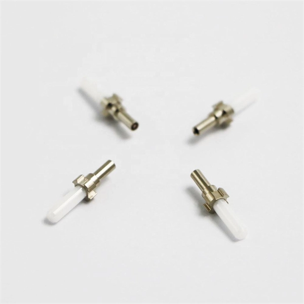
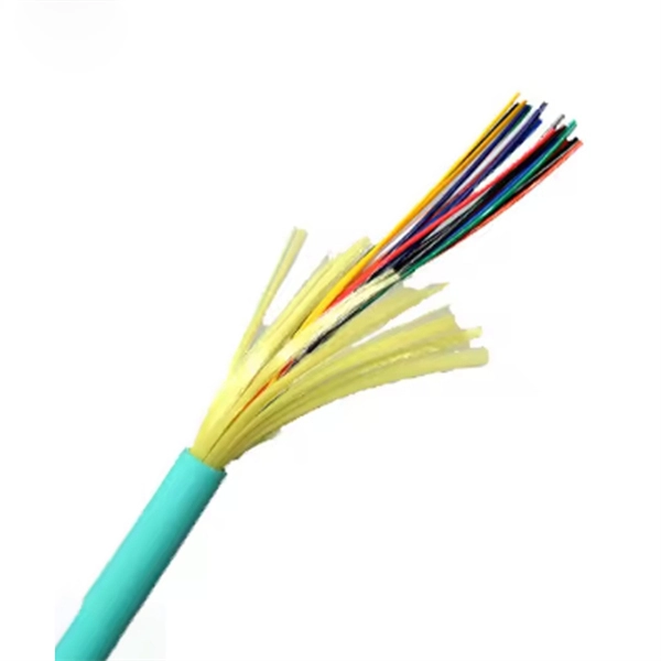
The operation and skills of fiber optic fusion splicing technology can be mainly divided into five steps: fiber stripping, fiber cutting, fiber melting, fiber sleeve, and fiber winding. In this guide, we cover the basics of fiber optic splicing, how to perform splicing using two different methods, and finally some best practices to perform good fiber splicing. What is Fiber Optic Splicing and Why is it Needed? – #1. And tools used for fiber fusion: fusion splicer; fiber cleaver; cable stripper; fiber optic stripper; alcohol;. Splicing fiber optic cable is an extremely important phase for making dependable, high-speed communication infrastructures. Regardless of the type of fiber network you're deploying, be it for telecom, enterprise data centers, or smart city infrastructure, fusion splicing provides the benefits of. While a cut or damaged fiber optic cable can temporarily take your network down, it is possible to quickly fix the cable with the right tools. In this video, we walk through the essential steps of preparing and splicing a fiber optic cable. Watch the complete process, from carefully stripping the fiber coating and performing a precision cleave, to loading the prepared fiber into the fusion splicer for a perfect alignment. Before jumping into the physical steps, it's important to understand the two primary methods of fiber splicing: fusion splicing and.
[PDF]
This guide covers the critical steps, from selecting the right electrical cable tray and performing accurate cable fill calculations to managing a safe cable pull through and ensuring all bonding and grounding requirements are met. en completely installed, without damage either to conductors or structural system use maintain spacing or to keep cables in place when the tray is ect the minimum bend ra-dius for cables as they exit the bottom of the cable tray. A rung spacing of 6 to 9 inches (150 to 230 mm) is preferable when. Article Summary: A compliant cable tray installation requires a thorough understanding of NEC Article 392, proper structural support, and precise installation techniques. But before you lay the first tray or clamp down a single cable, you need a solid plan. This guide breaks down the process step by step. Before installing a cable tray system, you need to consider a variety of factors to ensure everything works according to plan. The first thing you need to do is inspect all trays and accessories that you receive on-site. The equipment should be handled and stored according to the Project Procedure. Cable tray installation implies the construction of an electric road that will be safe. This is why proper planning and execution are.
[PDF]
High-voltage switchgear is any used to connect or disconnect a part of a. This equipment is essential for the protection and safe operation, without interruption, of a high voltage power system, and is important because it is directly linked to the quality of the electricity supply. The term "high voltage" covers the former medium voltage (MV) and the former high.
[PDF]

Powered by Al-driven algorithms, it automatically analvzes end-face imperfections, making it a critical tool for ensuring the reliability of CPO systems-supporting eficient data center operations and smarter future network infrastructure. • Additional connections for foot activation pedal & backplane handset extension. CleanBlastPRO™ is VIAVI's newest automated fiber end-face cleaning system, designed for seamless deployment by component and connectivity manufacturers and integrators. It ensures clean fiber connectors across. AFL offers a complete selection of compact fiber optic cleaning kits for field cleaning of connector end-faces and splicer v-grooves. We offer pre-stocked kits with a variety of cleaning tools and can also build you custom kits to meet your specific application needs. With a variety of kit options. Fiber connectors are precision components designed to carry light signals with minimal loss. Any debris, residue, or static can: Scatter or block light, leading to insertion loss. Create back reflections, which degrade signal quality. Scratch or pit the end face, causing permanent damage. Its large-field-of-view (FOV)design ensures full-core coverage in a single scan, while ultra-high-resolution optics accurately detect micron-level defects. Automated cleaners use a high-speed air/fluid mixture to flush contaminants from the endface, ensuring thorough, consistent cleaning. Fiber-optic technology has become the.
[PDF]

