An optical line termination (OLT), also called an optical line terminal, is a device which serves as the service provider endpoint of a passive optical network. It provides two main functions: to perform conversion between the electrical signals used by the service provider's equipment and the fiber optic signals used by the passive optical network.to coordinate the multiplexing between the conversion. FeaturesOLTs include the following features: • A downstream frame processing means for receiving and churning an cell to generate a downstream frame, and converting a parallel dat. Most vendors integrate an entire fiber optic management system for ISPs to manage OLTs as well as client ONTs and as such are not interoperable. • • BT-PON.
[PDF]
Unit shipments of 400G and 800G modules have grown nearly fourfold over the past 12 months and are expected to surpass 20 million for 2024. Cisco's NCS1K-OLT-C NCS 1010 Optical Line Terminal offers advanced C-band transmission for optical networks. With superior performance and reliability, it suits large-scale enterprise infrastructures and service providers. The Netherlands Optical Network Equipment market is estimated at approximately USD 1. 6 billion in 2026, driven by hyperscale data center expansion in the Amsterdam region and 5G transport network upgrades. Growth is projected at a compound annual rate of 8–11% through 2035, reaching USD 2. 5 billion by 2033, driven by a notable CAGR of 14. 0% between 2026 and 2033. Gain a. BOSTON (January 7, 2025) – Total shipments of leading-edge datacom optical modules are projected to tally over $9 billion for 2024, according to the latest Optical Components Report from research firm Cignal AI. 4% during the forecast period from. QSFP-DD optical module for reliable 400G fiber connections within ultra-fast setups, like the CRS812! Free Unisend Delivery to Latvia, Lithuania, and Estonia for Orders over €99. Free Posti Delivery to Finland for Orders over €199.
[PDF]

When it comes to testing fiber optic cables, a Visual Fault Locator (VFL) is an essential tool in your toolkit. A VFL is used to detect faults, breaks, or bends in fiber optic cables by emitting a bright red light that is visible even through the fiber's jacket. Let's dive into everything you need to know about mastering VFLs. In the. Finding a break in a fiber optic cable can be challenging but is essential for maintaining a stable network. Common Indicators of a Cable Break Signal. Here Kingfisher's experienced engineers share their experience in best practices and procedures for fiber optic testing related mostly to installation and maintenance. We hope that by sharing our knowledge, we will help grow our industry. Please enjoy & pass on these notes. The following are key methods and techniques used for optical fiber cable line failure positioning: Visual Inspection: Perform a visual inspection of the. Locating faults in fiber optic cables requires specialized tools and techniques. Look for dirt, scratches, or damage on the connectors. Clean. To ensure the quality and continuity of fiber optic services, it is essential to identify and locate fiber optic cable faults as quickly and accurately as possible. In this article, you will learn about some of the common methods and tools for fiber optic testing and troubleshooting.
[PDF]

Chile, in partnership with Google, is launching the Humboldt Cable System, the first fiber-optic submarine cable connecting South America with Asia and Oceania. As of 2025, the plan is to build a 14,800-kilometre (9,200 mi) cable from Valparaiso, Chile, to. The Humboldt Cable System is a 14810 km submarine cable connecting Chile, French Polynesia and Australia, with branches for the possible connection of other countries and territories. Stretching about 15,000 kilometers, it will connect Valparaiso, Chile, to Sydney, Australia, and then extend to Asia. Developed with H2. The company specializes in advanced fiber optic telecommunications and is dedicated to deploying fiber optic networks throughout Chile, enhancing broadband access for consumers and businesses. Their extensive ultra-broadband network, built to high industry standards, supports the digitalization. Google and the Chilean government have signed an agreement to install the Chile Submarine Humboldt Cable, a 14,800 km undersea fiber-optic line linking Valparaíso, Chile, with Sydney via French Polynesia. Slated for completion by 2027, it will be the first-ever direct South Pacific cable.
[PDF]

Search by part number or description such as CAT5, CAT6, OSP, etc. Sort by any of the table headers. Use the drop down menu to filter by product category and type. Sort by any. Welcome to the Corning LANscape® Solutions Product Drawings Resource Center, your complete source for our optical hardware component drawings. The two-dimensional and isometric hardware products drawings are available in PDF (Adobe® Acrobat®), DXF (AutoCAD®), VSS (Visio® Stencil) formats, and. Free CAD and BIM blocks library - content for AutoCAD, AutoCAD LT, Revit, Inventor, Fusion 360 and other 2D and 3D CAD applications by Autodesk. CAD blocks and files can be downloaded in the formats DWG, RFA, IPT, F3D. You can exchange useful blocks and symbols with other CAD and BIM users. When possible we have included both linear and nonlinear cable models for your use as appropriate. The use of a linear cable model may be acceptable for calculating loads and sags in an as-built situation such as joint use applications, or when linear elastic behavior and nominal creep are desired. The two linetypes are shown below. The appearance is similar but slightly different. Does anyone have such a code that they could share with me? I struggled for an hour or so and came up with this. There is a small gap on the left side of the circle.
[PDF]

Fiber optic terminal boxes provide functions such as input, branching and splicing of optical fiber cables. Through the connectors and splicing boxes in the terminal box, optical fibers can be quickly connected and repaired. Serving as a critical connection point, FTB facilitates the termination, splicing, or connection of fibers from various cables to other network devices such as switches, routers, or Optical Network Terminals (ONTs). It aids in splicing, splitting, storing, and managing fibers within the appropriate. The optical fiber terminal box is the terminal joint of an optical cable, one end of which is an optical cable, and the other end is a pigtail, which is equivalent to a device that splits an optical cable into a single optical fiber. A fiber pigtail is a specific hardware connection used for cable termination. It is a small enclosure that can house and protect the fiber optic cables, splices, and connectors. The optical fiber termination box and optical fiber splice box serve distinct purposes and are not interchangeable.
[PDF]

The transmitter optical power ranges from +3 to +7 dBm, while receiver sensitivity reaches -30 dBm, supporting distances up to 20 kilometers over standard single-mode fiber infrastructure. Note 1: Measured with 1310nm, 1. 244Gbps PRBS223- 1 burst-mode optical input, ER= 10dB, BER= 1x10⁻¹⁰; Single burst packet length is 40us and packet interval is 40us. Note 2: Input optical power level difference of adjacent burst packets. Note 3: Receiver optical power ranged from -8dBm to -28dBm. designed for FTTH GPON applications. Packaged in a Small Form- infrastructure in edge, enterprise, or distributed environments. robust fiber-to-the-home (FTTH) or small-scale fiber deployments. temperature, voltage, bias current, and optical power. On the uplink side, it operates. Max. Supporting 20km over single-mode fiber with 1490/1310nm wavelengths, this module delivers 33 dB link budget for 1:64 or 1:128 split ratios at 2. 488 Gbps downstream and 1. SC/PC connector for OLT PON port integration. Complete technical specifications and product details Our. Cisco ME Series products support any fiber-based (FTTx) access scenarios, including Fiber To The Home (FTTH), Fiber To The Building (FTTB), Fiber To The Curb (FTTC), Fiber To The cell (FTTc), and Fiber To The business (FTTb). Figure 1 illustrates the Cisco GPON solution. The Cisco GPON. The following tables list the performance specifications for the various functional blocks of the integrated optical transceiver module.
[PDF]
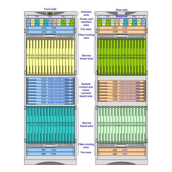
An OLT consists of three major parts: 1. Service port interface function - Provides translation between service interfaces and the TC frame interface of the PON section. 2. Cross-connect function - Provides a c.
[PDF]
Commonly, a power meter on its own is used to measure absolute optical power, or used with a matched light source to measure loss. When combined with a light source, the instrument is called an Optical Loss Test Set, or OLTS, typically used to measure optical power and end-to-end optical loss.OverviewAn optical power meter (OPM) is a device used to measure the power in an signal. The term usually refers to a device for testing average power in systems. Other general purpose light power measuring. The major types are (Si), (Ge) and (InGaAs). Additionally, these may be used with attenuating elements for high optical power testing, or wavelengt. A typical OPM is linear from about 0 dBm (1 milli Watt) to about -50 dBm (10 nano Watt), although the display range may be larger. Above 0 dBm is considered "high power", and specially adapted units may measure u.
[PDF]

The detailed steps outlined herein provide a comprehensive understanding of optical attenuator installation and adjustment. Proper execution enhances the efficiency and stability of the attenuators and the overall communication system. Fibre optic attenuators, also called optical attenuators, are passive devices used to reduce the power level of an optical signal. Assemble all necessary tools and equipment, such as a fiber cleaver, fusion splicer, optical power meter, and connector cleaning tools. These are the cornerstones of a seamless installation. Equally. Having a deep understanding of how to select a fiber optic attenuator, regardless of the type—fixed or variable—and the type of fiber and connector is critical to the durability and maintainability of a reliable network. Taking optical power measurements before installation of a fiber optic. Optical Signal Attenuation is the single greatest factor limiting the distance and performance of your network. Understanding it is crucial for anyone involved in data centers, telecommunications, or enterprise networking. In this. 📦 For purchasing, use the RP Photonics Buyer's Guide for optical attenuators. It provides an expert-curated supplier directory, buyer-focused technical background information, and structured selection criteria to support professional procurement decisions. Optical attenuators are devices that.
[PDF]

Urban Areas: 25–40m spacing (concrete poles, 10–12m height)., steel lattice structures). Factors: Cable weight (kg/km) Ice loading (up to 50mm. The Fiber Optic Association, Inc. (FOA) was founded in 1995 to help develop the workforce to build the fiber optic networks to support a rapid expansion in communications and the Internet. The charter of the FOA was to promote professionalism in fiber optics through education, certification, and. to n utral comm. cable R. FO-CS JOINT USE CLIMBING SPACE REQUIREMENTS 51. APPENDIX A - COVER SHEET / TOC 52. RUS DRAWING #PM12 58. CHECK. d suppliers of electrical construction services. They define a minimum baseline of quality and workmanshi for installing electrical products and systems. NEIS® are intended to be referenced in contrac documents for electrical construction ation or liability to users of this publication. Choose the type of pole The basic pole height is 7m and the tip diameter is 150mm. In case of special sections, crossing obstacles or roads or railways, the pole height of 8m, 9m, etc. can be selected. Cables 300 V or less need to be a minimum two feet over the street light. Climbing Space is an unobstructed, vertical space along the side or corner of the pole. In gen-eral, it consists of an imaginary box, 30-inches square, extending at least 40 inches above the highest communications cable or.
[PDF]

Managing optical attenuation helps keep your signal safe. Clean your optical connectors so you do not lose. Optical Signal Attenuation is the single greatest factor limiting the distance and performance of your network. Understanding it is crucial for anyone involved in data centers, telecommunications, or enterprise networking. This guide will demystify signal loss, explore its causes, and show you how. In high-speed environments, where the optical link budget is measured in fractions of a decibel, diagnosing and eliminating unexpected loss is the network engineer's most critical task. This field guide provides a systematic, step-by-step approach to troubleshooting and resolving the most common. Signal loss in Fiber Optic networks can make data slow. It can also break your connection. You should fix it fast to get speed and stability back. > You can solve this with simple steps. Signal Degradation (Loss of Light) When the signal quality degrades, it could be a sign of attenuation or excessive loss in the system. The signal might become weaker, resulting in slower speeds or dropped connections. -. Fiber optic networks are celebrated for their speed and reliability, but even the best systems can encounter problems. When issues like signal loss, slow speeds, or intermittent connectivity arise, systematic troubleshooting is key. Things like impurities in the fiber core and reflections at the core-cladding edge cause this drop.
[PDF]
As an essential component of optical fiber communication, optical modules are optoelectronic devices that facilitate the conversion between optical and electrical signals during the transmission process. Operating at the physical layer of the OSI model, optical modules are core devices in optical. The optical module serves as a crucial component in optical fiber communication systems, operating at the physical layer, which is the lowest layer in the OSI model. Classification of Optical Module: Distinguished according to function, package form, transmission rate, wavelength. In the era of 5G, AI, and high-speed data centers, optical modules serve as the core bridge for converting electrical signals to optical signals (and vice versa), enabling fast, reliable data transmission across networks. They are used in fiber optic communication systems to transmit data over long distances with minimal loss and interference. These modules typically consist of a laser or LED transmitter, a.
[PDF]


