In optical transmission systems, there are three key elements: the transmitter (laser and modulator), the photodetector, and the optical transmission medium (the fiber). Typically, the detector is characterized by a level of sensitivity to impinging optical power. However, as many optical channels travel in a fiber strand, many interesting phenomena take place. Light interacts with mat- of high quality, the received signal may have been contaminated. Therefore, the system and network. This is the second book on performance of optical channels, systems, and. Optical communication systems transfer information over distances using light instead of electrical current. These systems convert electrical signals, which carry data, into pulses of light and then back into electrical signals at the destination. The optical transmitter and the optical receiver. As an essential component of optical fiber communication, optical modules are optoelectronic devices that facilitate the conversion between optical and electrical signals during the transmission process. Most of the systems utilize a transceiver which. tion assisted by digital signal processing (DSP). The objective of this tutorial chapter is to briefly review the operating principles of state-of-the-art ong-haul coherent optical communications systems. Photonic systems are usually analyzed in terms of individual photons, although wave methods still.
[PDF]

Filter your results below. The 400G OSFP SR8 optical module supports speeds up to 425Gbps, short-range distance reaching up to 100m over 16 parallel multimode fiber (MMF) OM4. OSFP-400G-SR8 has an MTP/MPO-16 connector. 400G SR8 is designed based on PAM4 (Pulse Amplitude Modulation 4-level) modulation technology, DSP (Digital. MaxLinear's highly integrated PAM4 DSPs offer superior link-margin performance and low power to enable 100G, 400G, 800G, and 1. 6T optical interconnects inside the data center. NADDOD OSFP-400G-SR4 optical transceiver is a four-channel, parallel, pluggable fiber-optic OSFP with built-in Broadcom DSP and Broadcom VCSEL, designed for 400G Ethernet applications. It integrates four transmit and four receive lanes, each operating at 53. 125 GBd, delivering an aggregate. Support 100GBASE per lane in multimode fiber. Fibres: 8 fibres (ribbon patchord). Hot-pluggable OSFP Type form factor. Data rate up to 425Gbps (4x 10⁶. Connector: MPO-16/APC. Max reach: 100m, over multimode OM4 (MMF) fibre. This high-performance module is optimized for short-range data communication and interconnect applications, delivering exceptional speed and reliability. It integrates. The Marvell® PAM4 optical DSP portfolio, including Spica™ and Nova™ DSPs, addresses the critical the need for high-bandwidth optical interconnects to power AI infrastructure. Marvell leads the pluggable module ecosystem with low-power, high-performance silicon for AI, cloud, enterprise and 5G.
[PDF]

Creating a 90-degree elbow in an electrical cable tray, often called a "fabricated" or "mitered" bend, involves cutting, bending, and fastening a straight section of tray. The most common method involves creating two 45-degree cuts to form a 90-degree angle. Use this tool to estimate sloped section length, horizontal run requirement, cut marks, and installation feasibility. Measure this distance along the straight tray. Depends on the type of cable tray, you can buy 90° tray fittings or use a speed square with a straight edge and a grinder or skill saw to cut 45° cuts. Do you want a hard 90 or 2 spaced out 45° bends? Need dimension of tray first width x side wall. Also need to know if you're bending inside or. Key Concept/Formula: To create a 90-degree turn in a cable tray, a mitered joint is used, which involves cutting two pieces of cable tray at a 45-degree angle each. Key Concept/Formula: For a precise 45-degree cut, if the width of the. By applying the following formula you can quickly find the size of cut out section that you need to cut out of the side of the cable tray, or gutter-type section to make that angle. First, you have to find (C) which is found by dividing 90° by (B) 22° = 4. You can then calculate the size.
[PDF]

On average, you can rent a Fusion Splicer for $275/day, $773/week, $1424/month. The price of these splicers can be higher because of their mechanical complexity and ability to handle various fiber types, including large-core fibers. Hybrid splicers bring in various features that are present in both automatic splicers and manual splicers. They can be aligned by the core. Fiber optic fusion splicers are critical tools for deploying and maintaining fiber networks, with significant variations in performance, features, and pricing. This guide breaks down the key cost-influencing factors across five dimensions—splicer types, technology, performance, accessories, and. A fiber optic splicing machine is a specialized machine used to fuse two optical fibers together to form one long one. The machine, also known as a fiber optic fusion splicer, uses electricity to melt the two optic cables into one. The fiber fusion splicer conducts the fusion with high accuracy to. Check each product page for other buying options. Get reliable equipment with fast splicing times and comprehensive accessories included. It features a mini handheld design, integrated buttons and touch screen, simple operation, low.
[PDF]

The receiver of an optical module has an overload point. Therefore, an optical attenuator is required to reduce the optical power. By introducing a precise and constant amount of optical loss, it ensures that the incoming signal remains within the optimal operating range of the receiver. A. Average optical power refers to the optical power outputted by the optical module's transmitter under normal working conditions, which can be understood as the intensity of light. The transmitted optical power is related to the proportion of "1"s in the transmitted data signal; the more "1"s, the. The receiver of an optical module has an overload point. If the optical power received by the receiver is excessively high, the optical module will be burnt. In addition, during signal transmission in a WDM system, the. 📦 For purchasing, use the RP Photonics Buyer's Guide for optical attenuators. It provides an expert-curated supplier directory, buyer-focused technical background information, and structured selection criteria to support professional procurement decisions. Optical attenuators are devices that. An optical attenuator, or fiber optic attenuator, is a device used to reduce the power level of an optical signal, either in free space or in an optical fiber. Optical internetworks are data networks composed of routers and data.
[PDF]

Remove and reinstall the optical module. If the fault persists, replace the optical module with a normal one of the same type to check whether the optical module is faulty. The optical module is faulty or not securely installed. The device management or driver software has a bug. If the optical module is installed on a GE port, run the display interfaceGigabitEthernet x/x/x command to view port information when the optical module is inserted, including the rate and wavelength. Have you ever dealt with sudden network drops from faulty optical modules? Issues like this cannot only break communications, but they can really jeopardize business continuity. Understanding how to troubleshoot and prevent a failing optical module is vital for good network stability. This article. Huawei switches using non-certified optical module may not be able to read the information, can not guarantee the accuracy of the information read, recommend the use of Huawei certified optical switch module. Page 5 Changes in Issue 01 (2017-09-10) This issue is the first official release. The software version of this issue is V800R010C00. Issue () Huawei Proprietary and Confidential Copyright © Huawei Technologies Co. Page 8 40º C if a 40º C if a at 40º C if a single fan single fan single fan. The device cannot display any optical module information but services are running normally.
[PDF]
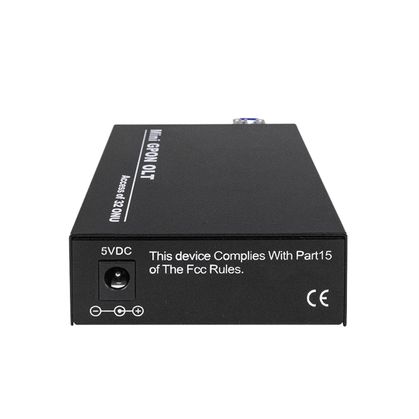
As an essential component of optical fiber communication, optical modules are optoelectronic devices that facilitate the conversion between optical and electrical signals during the transmission process. Operating at the physical layer of the OSI model, optical modules are core devices in optical. The optical module serves as a crucial component in optical fiber communication systems, operating at the physical layer, which is the lowest layer in the OSI model. Classification of Optical Module: Distinguished according to function, package form, transmission rate, wavelength. In the era of 5G, AI, and high-speed data centers, optical modules serve as the core bridge for converting electrical signals to optical signals (and vice versa), enabling fast, reliable data transmission across networks. They are used in fiber optic communication systems to transmit data over long distances with minimal loss and interference. These modules typically consist of a laser or LED transmitter, a.
[PDF]

Cost ranges for a residential fiber optic cable run typically span from $1,000 to $12,000, with most projects landing in the $3,000–$8,000 band. The main drivers are trench depth and length, whether the line is buried or aerial, and the in-home termination requirements. The main cost drivers are materials, installation time, and environmental factors that affect trenching, conduit, and terminations. This article provides cost. Installing an optical fiber network is a significant investment that requires careful financial planning. Whether you're upgrading an existing system or starting from scratch, understanding the costs involved can help you allocate your budget wisely. This guide will walk you through the key factors. How Much Does Fiber Optic Cable Cost per Foot? On average, commercial projects range from $5,000 to $20,000 per mile underground and $40,000 to $60,000 per mile for aerial deployment. Individual business connections often cost between $15,000 and $30,000 for 100–200 network drops. Hiring. Homeowners typically pay a broad range for running fiber optic cable from the street to a residence, with the main cost drivers being trenching or aerial installations, cable material, labor time, and permit requirements. The price also varies by fiber type (GPON vs. The price or cost to install fiber reflects material choices, labor hours, and local regulations, with per-mile and per-ft metrics common in.
[PDF]

Urban Areas: 25–40m spacing (concrete poles, 10–12m height)., steel lattice structures). Factors: Cable weight (kg/km) Ice loading (up to 50mm. The Fiber Optic Association, Inc. (FOA) was founded in 1995 to help develop the workforce to build the fiber optic networks to support a rapid expansion in communications and the Internet. The charter of the FOA was to promote professionalism in fiber optics through education, certification, and. to n utral comm. cable R. FO-CS JOINT USE CLIMBING SPACE REQUIREMENTS 51. APPENDIX A - COVER SHEET / TOC 52. RUS DRAWING #PM12 58. CHECK. d suppliers of electrical construction services. They define a minimum baseline of quality and workmanshi for installing electrical products and systems. NEIS® are intended to be referenced in contrac documents for electrical construction ation or liability to users of this publication. Choose the type of pole The basic pole height is 7m and the tip diameter is 150mm. In case of special sections, crossing obstacles or roads or railways, the pole height of 8m, 9m, etc. can be selected. Cables 300 V or less need to be a minimum two feet over the street light. Climbing Space is an unobstructed, vertical space along the side or corner of the pole. In gen-eral, it consists of an imaginary box, 30-inches square, extending at least 40 inches above the highest communications cable or.
[PDF]

This paper is focused on the performance analysis of protection mechanisms utilized in common wavelength division multiplexing-based passive optical networks. Wavelength division multiplexers are fundamental to the functioning and performance of integrated photonic circuits, with applications ranging from optical interconnects to sensing and quantum technologies. Current solutions are limited by trade-offs between channel spacing, crosstalk, insertion. Wavelength division multiplexing (WDM) is a technology for increasing the transmission capacity of optical fiber communications by sending multiple data channels simultaneously through a single fiber, each on a different wavelength of light. The main aim of the proposed research is providing an option of comparing different traffic protection scenarios for advanced optical. Herein, an attention-grabbing and up-to-date review related to major multiplexing techniques is presented which includes wavelength division multiplexing (WDM), polarization division multiplexing (PDM), space division multiplexing (SDM), mode division multiplexing (MDM) and orbital angular momentum. The journey of optical multiplexing began in the 1970s with the introduction of Wavelength Division Multiplexing (WDM), which revolutionized the capacity of optical communication systems. The primary objective of optical multiplexing has been to maximize the utilization of available bandwidth in.
[PDF]
A photonic integrated circuit (PIC) or integrated optical circuit is a microchip containing two or more photonic components that form a functioning circuit. This technology detects, generates, transports, and processes light. Photonic integrated circuits use photons (or particles of light) as. architecture and performance of several generations of InP-based PICs. Increased complexity in chip functionality has resulted in a need for increased fabricati n complexity from III-V epitaxy, through wafer fab, die fab, and test. Through continuous learning and improvement, Infinera has. Photonic integrated circuits (PICs) use light (photons) to transmit information, whereas traditional integrated circuits use electricity (electrons), enabling faster signal propagation. Whereas an electronic integrated circuit.
[PDF]
It provides a general plan for spectrum use and the basic structure to ensure efficient use of the spectrum and the prevention of radio frequency interference between services. Learn about the market conditions, opportunities, regulations, and business conditions in tajikistan, prepared by at U. Embassies worldwide by Commerce Department, State Department and other U. agencies' professionals Information and Communication Technologies (ICT) Tajikistan's ICT sector is. Satellite Internet Market Growth The global satellite internet market is experiencing steady growth, driven by increasing demand for reliable connectivity in remote and underserved areas. Through use of the table, manufacturers will have a guide to where in the spectrum to design and build equipment, and. Ministry of communications of Republic of Tajikistan We have an excellent working relationship with the Tajikistan Telecom Wireless Regulatory Authority, officials at Ministry of communications of Republic of Tajikistan. This means that we can ensure all your applications for Wireless Regulatory. On 7 April 2025, in Dushanbe (Tajikistan), Intersputnik, at the invitation of the Communication Service under the Government of the Republic of Tajikistan, attended the International Forum “Digital Transformation: Prospects and Solutions”. Intersputnik Director General Ksenia Drozdova held a.
[PDF]

6Wresearch actively monitors the Barbados Optical Fiber Cables Market and publishes its comprehensive annual report, highlighting emerging trends, growth drivers, revenue analysis, and forecast outlook. Our insights help businesses to make data-backed strategic decisions with. Equipment may be required for some packages & features. Pricing may vary depending on service area. Lifeline or Basic service needed for additional TV packages. Additional equipment may be required. Whether you are a professional or a DIY'er: at Kooyman we'll get you started! From home electronics to energy-efficient air conditioners, we have everything you need to power up your space. Our expertise extends to impeccable electrical finishing and electrical installations, ensuring your home. Barbados' leading IT, Computer & Consumer Electronics Superstore Retailer. From custom-surfaced prescriptions to ready-stock finished lenses, we provide comprehensive solutions for optical professionals. Available in single vision, bifocal, and progressive designs. Ready-to-edge stock lenses for. Moved Permanently. Redirecting to https://cartersonline. bb/electrical/cable-and-accessories/cables. Immerse yourself in a world of unparalleled variety as we offer an extensive array of extraordinary electrical products for your discerning needs. From top-notch outlets.
[PDF]

