Splice boxes keep joints of fiber-optic cables safe from external stress and manage excess cable lengths. They are also referred to as Optical Termination Boxes. The GZR Series 19" Rack-mounted Terminal Box (Rail-based) is a functional component for optical fibre distribution frames or network integrated cabinets, offering fibre splicing, distribution, and tray storage. CAHORS offers complete solutions for FTTH distribution in residential. OTRANS provides professional, high-quality rack mount fiber patch panels (also known as fiber termination boxes) designed for modern data centers and network infrastructure. Our comprehensive range, from 1U to 4U standard 19-inch panels, offers scalable port densities (12 to 96 ports) to meet your. Distribution Cabinet Box – The Multi-Operator cabinet is a grouping module for fusion, coupling and connection of up to 48 fibers. Our boxes serve as a connection point for incoming and outgoing cables, providing cable termination, organization, and protection. GAO's box includes features such as cable. With the growing global deployment of Fiber-to-the-Home (FTTH) networks driven by the demand for ensuring high-capacity broadband services, mobile network operators (MNOs) face challenges of excessive energy consumption (EC) of wired optical access networks (OANs). This paper presents a.
[PDF]

A distribution box, also known as a fiber distribution hub or optical distribution box, is a larger enclosure designed to manage and distribute fiber optic cables to multiple endpoints. It serves as a central point for connecting and organizing numerous fiber optic. Although all three are related to fiber connection and management, their installation locations, functional roles, and positions within the network architecture are fundamentally different. Confusing these devices may lead to non-standard cabling at best, and serious challenges in network. In modern FTTH (Fiber to the Home) and optical communication networks, three types of fiber distribution products are widely used: Splitter Distribution Box, ODF (Optical Distribution Frame), and Fiber Terminal Box. The functions of the four connectors can be. First, let us learn the common point among ODF, fibre optic termination box and fiber optical distribution box, actually, they have similar function, we sort out them as following 4 aspects: 1. fiber termination and optical signal splitting 4. What is the difference between these fiber boxes.
[PDF]

For a conventional optical module, we can easily judge the wavelength of the optical module from the color of the latch ring. For example, the black pull ring represents 850nm, and the blue pull ring represents 1310nm. Distinguish the wavelength by the color of the pull ring of the optical module In order to distinguish their own optical modules, different manufacturers can distinguish them by their wavelength, transmission distance, packaging, etc. In the complex infrastructure of data centers, optical modules are critical components that. The utility model discloses a pull ring device suitable for an optical module, and belongs to the technical field of optical communication. This article provides a professional guide on transceiver pull tab color codes by wavelength—spanning SFP, SFP+, CWDM, and BiDi modules—and introduces how LINK-PP standardizes. These modules convert electrical signals into optical signals, which transmit data over distances of fiber optic cables with minimal power loss. The topic of specifications and physical traits is one aspect of this question; another often-overlooked detail is the color of the pull tab. This modest. The ControlLogix® Architecture provides a wide range from high-speed digital to process control. The ControlLogix which allows input information and output status to Rockwell Automation recognizes that some of the terms that are currently used in our industry and in this publication are not in.
[PDF]

Small Form-factor Pluggable (SFP) modules are a cornerstone of modern high-speed networks, enabling flexible, hot-swappable fiber connections in dense deployments. This article reviews reliability, testing practices, and real-world considerations from a QA and MTBF perspective. We explore. Add Judgment Criteria of Reliability Test Results, vulcanizing Corrosion requirement and airborne Contaminants Test. Make some editorial modifications. 5 Stress Test Requirements for Optical Module Components. ABSTRACT: The Optical Internetworking Forum (OIF) has been instrumental in standardizing coherent optics at the physical layer, with the 400ZR implementation agreement (IA) being a significant achievement. This white paper reports on the performance evaluation of 400ZR and OpenZR+ pluggable modules. Linear pluggable optics have emerged as a transformative technology in the telecommunications and data center industries, representing a significant evolution from traditional transceiver architectures. This technology enables direct fiber-to-chip connections without the need for intermediate. Long Term Reliability Methodology of Next Gen Pluggable Optical Modules for PAM4 Applications in Hyperscale Datacenters V. The coherent optics landscape has gradually transitioned from engineered links on closed systems to today's multi-vendor, standards-driven ecosystem.
[PDF]
Optical modules are essential components in modern communication networks, enabling high-speed data transmission over fiber optic cables. As the demand for faster and more reliable internet and data services grows, understanding these devices becomes increasingly important. Optical modules typically have an electrical interface on the side that connects to the inside of the system and an optical interface on the side that connects to the outside. That is, metal medium communication represented by coaxial cables and network cables is gradually being replaced by optical fiber media. Composition of Optical Modules The optical module, known as Optical Transceiver in. The optical module serves as a crucial component in optical fiber communication systems, operating at the physical layer, which is the lowest layer in the OSI model. Its primary function is to achieve optoelectronic conversion by converting electrical signals into optical signals and vice versa.
[PDF]

The table below is a Cross Reference for all Palo Alto Networks Hardware Accessories and includes the Palo Alto Networks SKU, RoHS Compliance, Harmonized Tariff Schedule, ECCN and License information. Choose an option Alt text (alternative text) helps when people can't see the image or when it doesn't load. Aim for 1-2 sentences that describe the subject, setting, or actions. This is used for ornamental images, like borders or watermarks. Short description for people who can't see the image or. The merchandise under consideration is an optical transceiver, part# EOLP-1396-10-X. This item is a single mode transceiver in a small form-factor pluggable (SFP) module for serial optical data communications with an operating data rate of 11. 3Gbps and transmission distance of up to 10 km. The. Currently, the U. import Harmonized Tariff Schedule (HTS) code for optical modules is 8517. HTS website https://hts. gov/,searching for "8517. 00" shows the result "General Free1/", which indicates that attention should be paid to 9903. All parts listed below are RoHS compliant and meet the requirements of the current RoHS 2. How to Reduce Optical Module Costs | SFP & QSFP Cost Optimization Guide-Industry News-Sate Optics-Network Connectivity Solutions! In today's rapidly evolving network environments, reducing operational costs is a top priority for data centers, telecom operators, and system integrators.
[PDF]
These modules are designed to transmit 100G Ethernet signals across single-mode fiber over distances up to roughly 80 kilometers. The “BiDi” concept, short for bidirectional transmission, means that a single fiber strand carries traffic in both directions using different. The 80km SFP is a compact, hot-pluggable optical transceiver module standardized for long-distance fiber optical communication, with a maximum single-fiber transmission distance of 80 kilometers as its core performance indicator. It is designed to meet the interconnection needs of medium and. SFP (Small Form-factor Pluggable) modules have evolved beyond short-reach Ethernet, enabling reliable 80km and 120km links with optical performance, wavelength management, and power efficiency. This guide dives into the practicalities of 80km and 120km long-haul SFP modules, including key. It can reach up to 80km using single-mode fiber. This module is small and easy to swap. You can change it without turning off your network. The QSFP28-100G-ZR4 uses LAN-WDM technology. It sends many signals through one fiber. This makes your network. Cisco ® QSFP28 100G ZR extends 100GbE coherent links from QSFP28 ports reaching up to 80km over dark fiber and up to 300km over amplified Dense Wave Division Multiplexing (DWDM) links.
[PDF]
The two primary types of optical modules are pluggable and embedded modules. Pluggable or hot-swappable modules can be easily inserted or removed from a networking device without shutting it down. Embedded modules, on the other hand, are permanently attached to a device. An optical module is a typically hot-pluggable optical transceiver used in high-bandwidth data communications applications. Optical modules typically have an electrical interface on the side that connects to the inside of the system and an optical interface on the side that connects to the outside. The optical module serves as a crucial component in optical fiber communication systems, operating at the physical layer, which is the lowest layer in the OSI model. Its primary function is to achieve optoelectronic conversion by converting electrical signals into optical signals and vice versa. Operating at the physical layer of the OSI model, optical modules are core devices in optical. In general, you can categorize this as medical devices being reusable or disposable but I'm really focused on the visualization and imaging side of things. Really medical cameras, endoscopic devices, anything that's used to look on, at, or in the body. They are used in fiber optic communication systems to transmit data over long distances with minimal loss and interference. These modules are typically plugged into network equipment such as.
[PDF]

Incoming Distribution Cable: The fiber distribution box receives an incoming distribution cable, which typically carries a bundle of optical fibers. These optical fibers originate from a central source, such as a data center, central office, or distribution point. Fiber Distribution Boxes (FDBs) are critical components in modern telecommunications infrastructure, particularly in fiber optic networks. Minimize the interference of the optical cable access signal to the external environment. The. In the complex architecture of fiber optic networks, the Optical Distribution Frame (ODF) serves as the linchpin for organizing, protecting, and distributing optical signals. Whether in data centers, telecom central offices, or enterprise network rooms, ODFs enable efficient fiber management. An optical cable consists of three primary parts: the core, the cladding, and the protective sheath. Surrounding the core is the cladding, which has a lower refractive index than the core. This complete guide explores everything you need to know about ODFs — from their structure, types, and key components, to installation best practices and modern design trends. Whether you're building a central office, data center, or FTTx distribution network, understanding the right ODF.
[PDF]

Many EMC failures can be avoided by considering EMC from the earliest project stages. This guide explains why EMC problems occur, how they typically appear at the PCB and system level, and what practical steps can help teams achieve reliable, compliant designs. The EMC (Electromagnetic Compatibility) for Optical Market occupies a critical niche within the broader semiconductor industry, primarily focusing on ensuring that optical components and systems operate reliably without electromagnetic interference. Today's electronics are smaller. However, as camera technology advances—with higher resolutions, faster frame rates, and integration into compact designs—ensuring Electromagnetic Interference (EMI) and Electromagnetic Compatibility (EMC) compliance has become increasingly challenging. Non - compliance can lead to performance. ► Electromagnetic compatibility (EMC) is an important criteria of product safety and quality. It is mandatory in the product certification process. ► The equipment under test “EUT” can have anomalies. Electromagnetic interference (EMI) and electromagnetic compatibility (EMC) issues impacting the design and pro-duction of consumer, industrial, and aerospace/defense de-vices is likely to become even more pervasive and common as industrial and governmental standards and electronic device density.
[PDF]
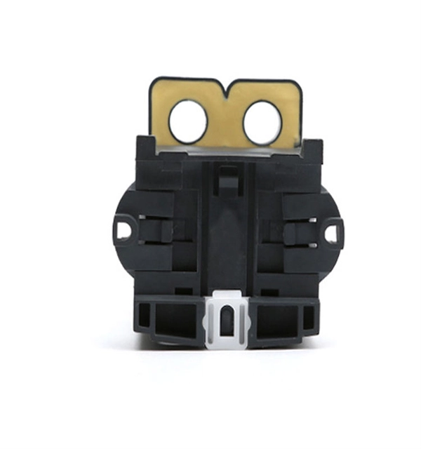
The aluminium alloy joint box are applicable for connection protection of special optical cables,with the functions of direct and branch connection, with the maximum of 6 optical cables, which mainly for overhead rods and towers. Explore top-quality OPGW hardware fittings, setting a new standard for secure and efficient connections in our Pole Line Hardware. The joint box is made of aluminium alloy and has a maximum capacity of 192 fibre splices. A pre-moulded neoprene anti-aging gasket. No. 77, East District, Sixian Industrial Zone, West Ring Road Office, Renqiu City,. An assembling plate trays is placed inside the box. Cable glands and a heavy wall OPGW cables. The anchoring of the joint box to the tower is poles. It features in high mechanical strength, good airtight and anti-corrosive. Having been sealed with sealing ring and silicone, it could be opened, expansed, fixed, and connected repeatedly. It's suitable in aerial. Optical cable junction boxes play a crucial role in connecting and protecting optical fibers, directly influencing the quality and lifespan of optical cable routes. Optical cable splice boxes protect the splicing parts of optical fibers from various hazards, such as water seepage due to adverse.
[PDF]

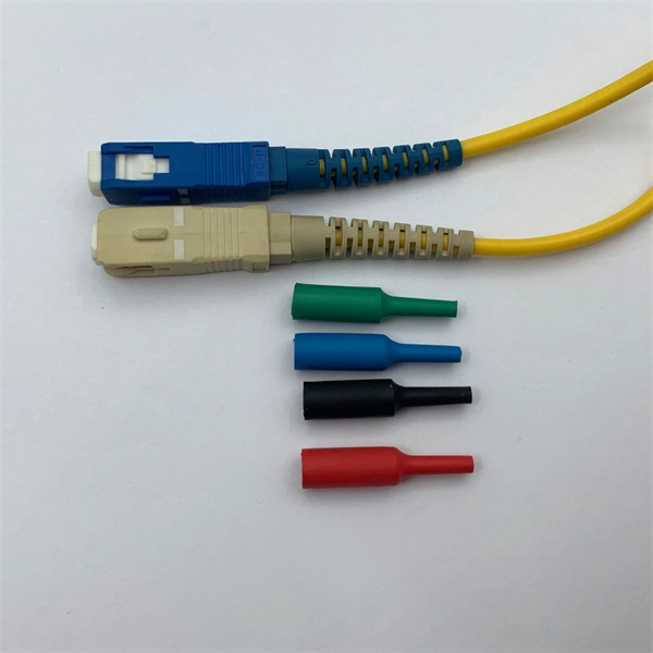
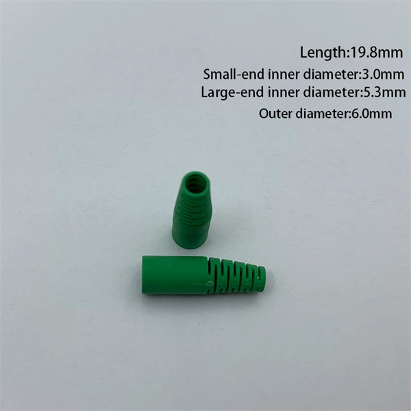
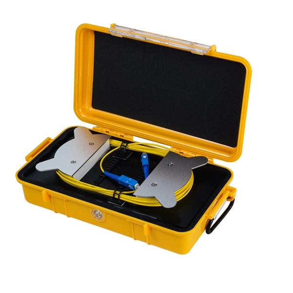
A Fiber optic cap type splice box is a protective enclosure designed to house and organize fiber optic splices. It typically features a dome or cap-style closure that provides a sealed environment for fiber joints, protecting them from external conditions. As fiber optic networks continue to expand across urban, rural, and industrial environments, the reliability of connection points becomes. The cap-type splice box is mainly designed for laying optical cables in overhead and tunnels. It does not meet the waterproof requirements of the regulations when used in direct-buried lines, but the moisture-proof effect in lines is better. According to regulations, the open type and other three. The types of optical cable splice boxes can be divided into cap-type optical cable joint boxes and horizontal optical cable joint boxes according to the shape and structure. According to. Grandway's fiber optic closure provides a high density wall mounted or pole mounted solution for next generation networks, which aims to provide and manage fiber splitters in a limited space. It is designed for FTTH (Fiber to the Home) or FTTB (Fiber to the Building) with protective housing for all. Briefly explain how fiber splice closures are critical for network protection and performance optimization. Introduce that choosing between dome (cap-style) and horizontal (in-line) closures depends on specific project requirements. Understanding Fiber Splice Closure Types 1.
[PDF]

In this step-by-step tutorial, we show you exactly how to place a fusion splice safely and securely inside a Coyote fiber optic splice enclosure. Fiber cable splicing is a critical step in building reliable fiber optic networks. Whether in data centers, telecom rooms, or outdoor FTTx deployments, proper splicing inside a fiber enclosure ensures low signal loss, long-term stability, and easy maintenance. This guide explains what fiber cable. Think of a fiber optic cable splice as the seamless stitching that keeps data flowing through the delicate threads of a network—like a master tailor joining fabric with precision. Whether repairing a broken cable or extending a fiber run, fiber optic splicing ensures light signals travel. In addition to the outer skin of the optical cable (if any, please remove the shielding and armoring) and then remove each wrapping layer until the loose tube is exposed. Make sure you read and understand this instruction as well as instructions provided with related assemblies before. In this guide, we cover the basics of fiber optic splicing, how to perform splicing using two different methods, and finally some best practices to perform good fiber splicing. What is Fiber Optic Splicing and Why is it Needed? – #1. Use and Maintain Your.
[PDF]
