
This guide covers everything: what fiber optic pigtails are, how they differ from patch cords, which connector and polish type to specify, how to choose between mechanical and fusion splicing, and the real-world applications where pigtails are the right call. In this guide, we cover the basics of fiber optic splicing, how to perform splicing using two different methods, and finally some best practices to perform good fiber splicing. What is Fiber Optic Splicing and Why is it Needed? – #1. Whether you're building out an ODF. Think of a fiber optic cable splice as the seamless stitching that keeps data flowing through the delicate threads of a network—like a master tailor joining fabric with precision. Whether repairing a broken cable or extending a fiber run, fiber optic splicing ensures light signals travel. Fibre optic splicing is an essential skill in the world of modern telecommunications, offering a reliable method to connect optical fibres for seamless data transmission. As the demand for high-speed internet and robust communication networks continues to grow, learning to splice fibre optics is. In this guide, you will find a chronological description of the fusion splicing process, the principal technical standards, and answers to the real-life questions network engineers and procurement teams may have. Therefore, we will also touch on cost factors, risk management, and best practices in.
[PDF]

In this guide, you will find a chronological description of the fusion splicing process, the principal technical standards, and answers to the real-life questions network engineers and procurement teams may have. 📦 For purchasing, use the RP Photonics Buyer's Guide for fusion splicers. It provides an expert-curated supplier directory, buyer-focused technical background information, and structured selection criteria to support professional procurement decisions. This article explains the principle of fusion. Fusion splicers play a crucial role in the field of optical fibre communications by enabling the permanent bonding of two strands of glass fibre to create a continuous pathway for light to travel through. This process is achieved through precise alignment and fusion of the fibre ends using an. Fusion splicing is the process of fusing or welding two fibers together usually by an electric arc. Fusion splicing is the most widely used method of splicing as it provides for the lowest loss and least reflectance, as well as providing the strongest and most reliable joint between two fibers. Each splicer is equipped with a cleaver and stripper, conveniently includes in a single case. The goal is to align the microscopic glass cores (typically.
[PDF]

Main cost drivers include on-site labor, specialized fusion splicing, testing, and any necessary restoration of network performance. This guide provides practical cost ranges in USD with clear low–average–high estimates to help budgeting and planning. Fiber optic splicing costs vary widely depending on project size, location, fiber type, and site conditions. For most commercial projects, expect to pay $50–$150 per fusion splice point — but that number can swing in either direction based on the factors below. The "per splice" rate is the most. There are two primary methods of splicing fiber optic cables: fusion splicing and mechanical splicing. Each method has distinct characteristics and costs associated with it. Fusion Splicing: This method involves aligning two fiber ends and using an electric arc to melt them together, creating a. Adtell Integration is capable of supporting your fusion splicing requirements whether they require Singlemode, Multimode, or Ribbon Splicing. Fusion Splicing Services: Contractor/Customer Fusion Splicing & Installation Services: Adtell integration offers nationwide fusion splicing services. Specifically fiber used for internet. -W2 employee for a decent size telecommunication contractor, all.
[PDF]
Fiber optic splicing is the process of joining two fiber optic cables together so that light signals can pass with minimal loss or reflection. Splicing is typically required during cable installation, maintenance, or network expansion. Another method of connecting optical fibers is termination or connectorization, which consists of processing the end of a fiber optic bundle so that it can be connected to other fibers or devices through fiber optic. When deploying fiber optic cabling, one of the most critical decisions is how to terminate the fiber—either by splicing or using connectors. Both techniques have their advantages and are suited for different applications, but understanding which method to use can greatly impact the network's. Fiber optic splicing, crucial for maintaining seamless connectivity in modern communication networks, primarily uses two methods: fusion splicing and mechanical splicing. Fusion splicing provides a low-loss, highly reliable connection by melting and fusing fiber ends, making it ideal for long-haul. As fiber optic connections become increasingly mainstream, the need to connect fiber optic cables to one another — or splicing — is also on the rise. Get the wrong connector type, the wrong polish, or skip proper fusion splicing technique—and you're looking at elevated signal loss, increased back reflection, and a.
[PDF]
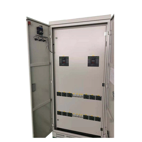
Manufacturers design fiber optic cabinets to protect fiber optic cables in indoor and outdoor environments. Also known as fiber optic enclosures or fiber entrance cabinets, these enclosures act as hubs where ca.
[PDF]

It is a technique that uses controlled heat to permanently fuse two optical fiber ends together. Unlike mechanical splicing, which relies on alignment sleeves and index-matching gel, this thermal approach creates a continuous glass path between fibers. Optical fiber transmission has the advantages of wide transmission frequency, large communication capacity, low loss, no electromagnetic interference, small diameter of optical cable, light weight, rich source of raw materials, etc., so it is becoming a new transmission medium. When light is. Common splicing methods include optical fiber cold splicing and optical cable hot fusion splicing. Advantages and disadvantages of fiber optic cold splicing Fiber cold splicing refers to using special tools to mechanically connect two optical fibers. Its advantages include: Simple operation and. This is part 6 of a tutorial on passive fiber optics from Dr. The tutorial has the following parts: Optical fibers can be joined together, such that light is efficiently transferred from one fiber to another. There are various possibilities: Mechanical splicing means that two fiber ends. This guide reveals the secrets to fusion splicing with little fluff—just proven, straightforward techniques refined from years of work in the field. The result is a joint that closely matches the.
[PDF]
Because fiber optic cables don't come in one continuous length, sections must be joined together through splicing. This process fuses two glass strands so light signals can travel through them without interruption. Below is a detailed look at each step of fiber optic network construction, including key terms and methods used across the industry. Engineers and. We are experts in the installation and use of fiber optic cable to residences, apartment buildings, businesses and cell sites. We complete complex construction projects consisting of aerial and underground deployments in varied, often difficult, working environments. Our services include everything. The Fiber Optic Association, Inc. (FOA) was founded in 1995 to help develop the workforce to build the fiber optic networks to support a rapid expansion in communications and the Internet. Delivers state-of-the-art fiber optics solutions by developing high-tech equipment and subcontractor expertise. Utilizes state-of-the-art technologies to splice a wide variety of different. This recommended practices document is a comprehensive manual for optical fiber construction and testing. Sections are included for project management; cable handling, testing and equipment; overhead cable placement; underground cable placement; underground enclosures; bonding and grounding; cable. 4. FO-VC2 JOINT USE - VERICAL MIDSPAN CLEARANCES 48. FO-GB GROUNDING AND BONDING 49.
[PDF]

The Optical Time Domain Reflectometer (OTDR) is useful for testing the integrity of fiber optic cables. It can verify splice loss, measure length and find faults. The OTDR is also commonly used to create a "picture" of fiber optic cable when it is newly installed. The Contractor tasked to perform testing or splicing on any fiber optic cable will follow these testing standards to fulfill their contractual obligations. The Contractor must utilize the correct equipment and testing techniques to gain acceptance, or the work cannot be approved. Later, comparisons can be made. For every fiber optic cable plant, you will need to test for continuity, end-to-end loss and then troubleshoot the problems. If it's a long outside plant cable with intermediate splices, you will probably want to verify the individual splices with an OTDR also, since that's the only way to make. ic system. Fiber optic testing of a newly installed system not only verifies that the system meets its design requirements, but also creates a performance baseline for all future testing and troubleshooting of t at system. What is Fiber Optic Splicing and Why is it Needed? – #1. Use and Maintain Your. This guide reveals the secrets to fusion splicing with little fluff—just proven, straightforward techniques refined from years of work in the field. The guide provides the complete workflow, covering safety precautions, tool selection, fiber preparation, fusion operation, quality control, and.
[PDF]

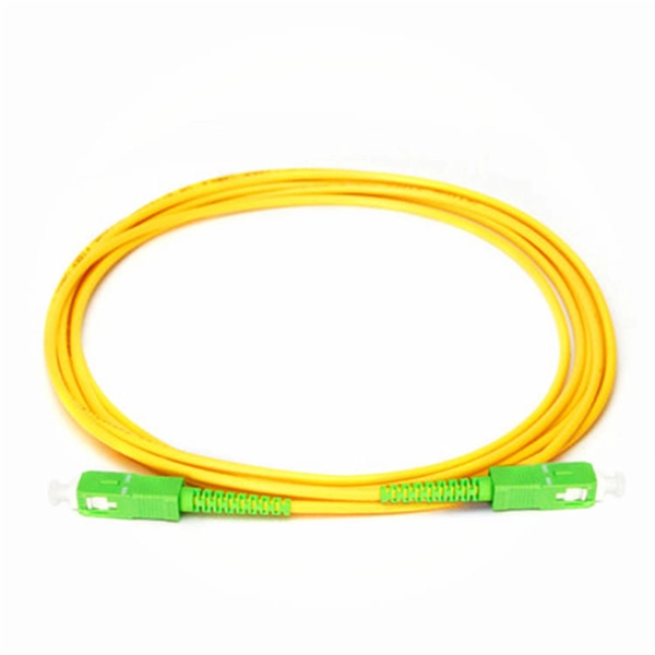
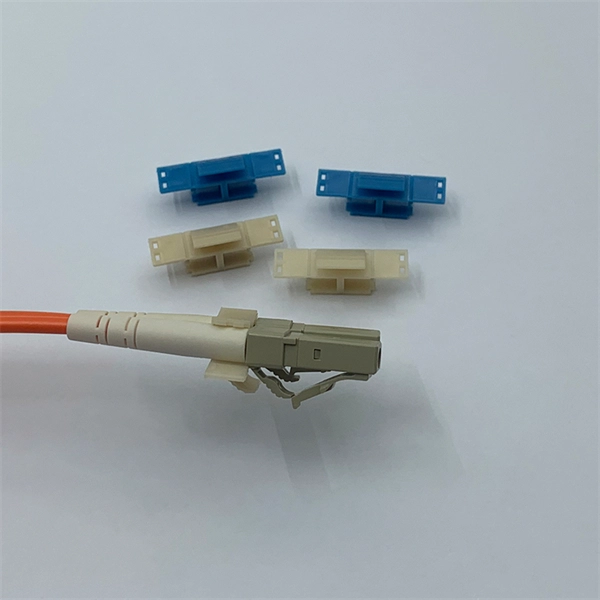
In this article, we will provide you with a step-by-step guide on how to install and remove fiber optic connectors properly. Step 1: Prepare the necessary tools and materials, including the fiber optic connector, cable stripper, fiber cleaver, and lint-free wipes. HomeNetworking is a place where anyone can ask for help with their home or small office network. No question is too small, but please be sure to read the rules before asking for help. We also welcome pretty much anything else related to small networks. I have this connector on my optic fibers cable. Terminating fiber optic cables essentially means putting connectors on fiber optic cable so that you can connect the cable to various devices or network components. Think of it as the equivalent of connecting the dots in a complex puzzle; without proper termination, the whole system can break down. The fiber optic tool kit contains tools to assemble SC connectors. Required consumables are sold separately. Consumables Kit: The consumables kits for single mode and multimode connectors are show below. If the connector is broken, it might need to be replaced rather than taken out. Removing these connectors requires care to avoid damaging the delicate fibers or the connector itself. Ensure that everything is clean.
[PDF]

This guide explains fiber optic cable construction, the difference between tight buffer and loose tube structures, and compares eight common cable types used in data centers, enterprise networks, and FTTH deployments. The Fiber Optic Association, Inc. (FOA) was founded in 1995 to help develop the workforce to build the fiber optic networks to support a rapid expansion in communications and the Internet. The charter of the FOA was to promote professionalism in fiber optics through education, certification, and. 40. FO-VC2 JOINT USE - VERICAL MIDSPAN CLEARANCES 48. FO-GB GROUNDING AND BONDING 49. APPENDIX A - COVER SHEET / TOC 52. Building a fiber optic network is a highly technical yet vital process that enables communities and businesses to access high-speed, reliable fiber optic internet. From the initial site survey to the final fiber to the home (FTTH) connection, every stage requires careful planning, coordination, and. Fiber optic cables facilitate high-speed connectivity with significant advantages over copper wires, such as faster data transmission, greater bandwidth, and better security; single-mode fibers are ideal for long distances, while multi-mode fibers suit short-range communications. Proper fiber optic. Fiber optic cables come in many designs depending on where and how they are deployed. The method covers the steps from receiving the materials on the installation site and cable pulling as per the approved shop drawings.
[PDF]
The applicable subheading for the fiber optic panel/chassis and fiber optic patch tray, will be 9403. 8040, Harmonized Tariff Schedule of the United States (HTSUS), which provides for “Other furniture and parts thereof: Parts: Other: Other; Of metal. ” The rate of duty will be free. Item 1, part number LCXE-M1RU-BLK, is described as a fiber optic chassis with the capabilities of holding twelve fiber optic cables. The panel is produced from cold rolled. The merchandise is fiber optic patch panels that provide a consolidated point of demarcation for optical terminations, connections and cross connections within a passive, fiber optic network. They are designed to be mounted onto a wall or rack. All fiber optic patch panels will consist of the. Find verified buyers and sellers of Fiber Optic Patch Panel in 180+ countries along with their valid phone numbers and email ids. The top 3 Buyer countries for HS Code 851770 are “ PHILIPPINES ”, “ INDIA ”, “ PAKISTAN ”,. com if you have any questions or special project needs. The panel is produced from cold rolled. In the United States, customs duties imposed on imports from Asian countries have increased costs for Internet service providers and telecommunications companies, in many cases delaying infrastructure expansion and maintenance projects. In Latin America, several countries have adopted tariff.
[PDF]
Fiber Optics Market was valued at USD 8. 1 billion in 2023 and is anticipated to grow at a CAGR of over 5% between 2024 and 2032. The demand for high-speed broadband access is accelerating with end-users increasingly seeking high-quality multi-gigabit services to power their homes and. Fiber Optics Market was valued at USD 8. Cartesian received input to this study from across the industry and nation. Respondents spanned the fiber construction ecosystem from. Market Size by Fiber Type (Glass Fibers, Plastic Optical Fibers), by Cable Type (Single-mode, Multi-Mode), by Deployment (Underground, Aerial, Underwater) by End User & Forecast. 8 billion by 2029 from USD 3. 4% from 2024 to 2029. Rapid expansion of data centers, cloud services, and 5G infrastructure is driving strong adoption of fiber optic solutions. The global deployment of 5G networks by telecommunications.
[PDF]

Explore verified suppliers offering low-price fiber optic splice boxes, ideal for wholesale. With options from 24 to 144 cores, start your purchase from 1 unit at an average price around $17. TAKFLY COMMUNICATIONS CO. com! Source over 176 fiber-optic splice closures for sale from manufacturers with factory direct prices, high quality & fast shipping. We support our B2B partners with OEM branding, custom configurations, and bulk order discounts, delivering factory-tested solutions for large-scale. COYOTE Closure, 288f/576f ribbon max, Buffer Tube: 8. 5″ x 22″, Includes (1) 3 Section End Plate, (1) Blank End Plate, Organizer, and Lock Tape sealant. FOSC 600 D Dome Closure, 648ct Single/1728ct Ribbon, 8 Ports, Loaded Without Trays, 4 Ground Lugs, 32. 79″, Price Per Ea. ZIP code to view pricing. ZIP code to. Budco is a stocking distribution company for broadband tools, fiber optic tools and cable tools. Since 1970, Budco has provide cable construction tools, cable installation tools, and cable identification tools including fiber optic test equipment and tools for the telecommunications industry. We. This fiber optic splice box is an outdoor fiber optic splice closure used to protect the twisting and joining (splicing) of fiber optic cables. These splice boxes are not made for in-house, off-the-shelf cabling solutions. Instead, they are for installation by professionals laying new fiber optic.
[PDF]

