Busbars operate as conductive bars that distribute electricity from incoming feeders to outgoing circuits within an electrical system. By providing a low-resistance path, busbars ensure efficient current distribution with minimal power loss. These components are typically mounted within an. Electrical busbars are solid conductors used to carry and distribute high current in switchgear, panels, substations, and power systems. This guide explains how busbars work, common types, key design factors, and how to choose the right busbar for your application. An electrical busbar is a solid. The busbar electrical system performs several essential functions that support efficient power management: Power Distribution: It is a central station to which the electrical power is brought out of one source and to more than one circuit. Existing Transmission: Electric busbar transmits huge. I. Basic Definition of the Small Busbar at the Top of the High-Voltage Cabinet The small busbar at the top of the high-voltage cabinet, as the name suggests, is a small busbar device installed at the top of the high-voltage switchgear. Its primary role is to carry large current loads and connect multiple circuits together. Think. An electrical busbar functions as a metallic conductor, playing a pivotal role as a central link for multiple electrical connections. These connectors can take on various forms including solid, hollow, or even flexible designs to suit different needs.
[PDF]
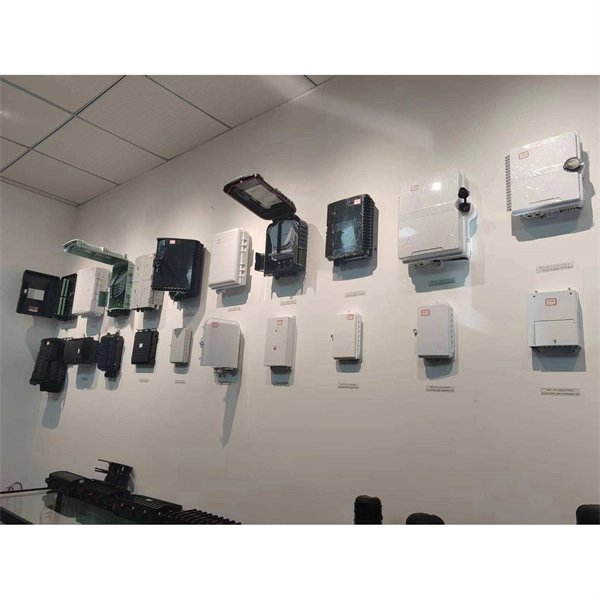
The aluminium alloy joint box are applicable for connection protection of special optical cables,with the functions of direct and branch connection, with the maximum of 6 optical cables, which mainly for overhead rods and towers. Explore top-quality OPGW hardware fittings, setting a new standard for secure and efficient connections in our Pole Line Hardware. The joint box is made of aluminium alloy and has a maximum capacity of 192 fibre splices. A pre-moulded neoprene anti-aging gasket. No. 77, East District, Sixian Industrial Zone, West Ring Road Office, Renqiu City,. An assembling plate trays is placed inside the box. Cable glands and a heavy wall OPGW cables. The anchoring of the joint box to the tower is poles. It features in high mechanical strength, good airtight and anti-corrosive. Having been sealed with sealing ring and silicone, it could be opened, expansed, fixed, and connected repeatedly. It's suitable in aerial. Optical cable junction boxes play a crucial role in connecting and protecting optical fibers, directly influencing the quality and lifespan of optical cable routes. Optical cable splice boxes protect the splicing parts of optical fibers from various hazards, such as water seepage due to adverse.
[PDF]
In this paper, we present this new method of building OMS-OOCCN or its model. System design Our method applies three key information processing techniques such as geographic information system (GIS), simulation and expert system (ES) ones. We developed a specialized Geographic Information System for an internet service provider operating a fiber-optic network across multiple neighboring locations. Really, they are also the most important techniques for. Location Data (C. Summary of descriptive data (C. Manage Fiber Optics Network (maintenance &operation) (C. Final. A leading telecom infrastructure provider responsible for planning, deploying, and maintaining optical fibre cable (OFC) networks to expand digital connectivity across urban and rural regions. The client needed a reliable and accurate system to document, monitor, and manage thousands of kilometers.
[PDF]

Optical attenuators use several principles in order to accomplish the desired power reduction. The types of attenuators generally used are fixed, stepwise variable, and. An optical attenuator is a passive device that is used to reduce the power level of an optical signal. The attenuator circuit will allow a known source of power to be reduced by a predetermined factor, which is usually expressed as decibels. Key requirements include minimal effect on the beam profile, low wavelength and polarization dependence, and sufficient power handling capability. The basic types of optical attenuators are fixed, step-wise variable, and continuously variable. Since too much light may saturate the fiber optic receiver, optical attenuators are often deployed in the system to reduce the light power and achieve the best fiber. An attenuator is a device designed to reduce the intensity of electrical and electromagnetic oscillations smoothly, stepwise, or at a fixed rate. It primarily ensures the power or amplitude of a signal is lowered without significantly distorting its waveform. Attenuators are extensively used across.
[PDF]

This guide provides CISOs and IT leaders with an in-depth look at network security architectures. Perimeter security is the first line of defense, protecting the network from external threats. It includes firewalls, intrusion prevention systems (IPS), and other security devices that control network traffic at the network's boundary. When effectively designed, network security reduces threats like unauthorized access and malware from impacting your network or. Network security architecture is a strategy that provides formal processes to design robust and secure networks. Effective implementation improves data throughput, system reliability, and overall security for any organization. It explains the key concepts in plain language, dives into the core components, shares a framework for. Microsoft Defender for Cloud provides cloud security posture management (CSPM) and cloud workload protection (CWP). It assesses your resources for security compliance, provides a secure score to track your posture, and offers threat protection across Azure, on-premises, and multicloud workloads. It encompasses hardware, software, policies, and procedures.
[PDF]

Relay protection is the discipline of designing schemes that detect faults, coordinate relays, and isolate equipment without outages. It emphasizes selectivity, coordination, fault response, and system behavior rather than individual relay devices. Relay protection is often misunderstood as a. A protective relay is an intelligent electrical device designed to detect faults in power systems and initiate corrective actions such as tripping a circuit breaker. : 4 The first protective relays were electromagnetic. This document provides recommendations, background and philosophy on relay protection that is not available in M07. The facilities to which this Document applies are generally comprised of the fol-lowing: In analyzing the relaying practices to meet the broad objectives set forth, consideration must. What is a Protective Relay? A protective relay is an intelligent device that senses abnormal electrical conditions, such as overcurrent, under-voltage, or frequency deviations. It initiates the operation of circuit breakers to isolate the affected section. This prevents damage to equipment, reduces. Protective relays and devices have been developed over 100 years ago to provide “lastline”of defense for the electrical systems. They are intended to quickly identify a fault and isolate it so the balance of the system continue to run under normal conditions. The selection and applications of.
[PDF]
Most modern photometers detect light by converting it into an electric current using a photoresistor, photodiode, or photomultiplier. Some models employ photon counting, measuring light by counting individual photons. They are especially useful in areas where the irradiance is low.OverviewA photometer is an instrument for measuring quantities such as,, or. Historically, photometry was done by estimation, comparing the luminous flux of a source wi. Before electronic light sensitive elements were developed, was done by estimation by the eye. The relative of a source was compared with a standard source. The photometer is placed such that th. Most photometers detect the light with, or. To analyze the light, the photometer may measure the light after it has passed through a or through a.
[PDF]

Beam splitters are classified by construction (plate, cube, pellicle, polka dot) and by function (standard, non-polarizing, polarizing, dichroic). Construction determines ghosting, damage threshold, and form factor. Function determines how polarization and wavelength are. Beamsplitters are optical components used to split incident light at a designated ratio into two separate beams. Additionally, beamsplitters can be used in reverse to combine two different beams into a single one. Beamsplitters are often classified according to their construction: cube or plate. A beam splitter or beamsplitter is an optical device that splits a beam of light into a transmitted and a reflected beam. It is a crucial part of many optical experimental and measurement systems, such as interferometers, also finding widespread application in fibre optic telecommunications. This division allows for the simultaneous analysis or utilization of the light's properties along two separate paths. These versatile tools can split both laser and regular light, depending on the application in question. Its fundamental purpose is to precisely control the path and intensity of light, making it a ubiquitous component across various optical systems. For a lossless beam splitter, R + T = 1. When comparing beam splitters, always check whether the specified R/T ratio is for unpolarized light or for a specific polarization. The numbers can differ.
[PDF]

The fiber optic cable core is the physical glass medium that transports optical signals from an attached light source to a receiving device. The light is transported along the optical fiber via its smallest and most crucial component, which is called the core. The modern digital world relies heavily on fiber optic cables, which serve as the high-speed backbone for global communication. Professionals in telecommunications, data centers, and network infrastructure must understand the core functions and why they are fundamental to their fiber optic. A fiber optic cable consists of five basic components: the core, the cladding, the coating, the strengthening fibers, and the cable jacket. When searching for a fiber optic cable, we need to pay attention not only to the connectors, such as SC to ST fiber cable, LC to SC fiber patch cable, or SC to. The reason is that cores are basically hidden components located that receive the light signals. Don't worry, in this guide, we'll discuss in detail what the fiber optic core is and its role in data transmission. Moreover, we'll also explore the different types of fiber optic cores available as. The core of a conventional optical fiber is the part of the fiber that guides the light. It is a cylinder of glass or plastic that runs along the fiber's length. The core is surrounded by a medium with a lower index of refraction, typically a cladding of a different glass, or plastic.
[PDF]
A fiber-optic sensor is a that uses either as the sensing element ("intrinsic sensors"), or as a means of relaying signals from a remote sensor to the electronics that process the signals ("extrinsic sensors"). Fibers have many uses in. Depending on the application, fiber may be used because of its small size, or because no is needed at the remote location, or because many sensors can be along the length of a fiber by using light wavelength shift for.
[PDF]
In , a busbar (also bus bar) is a metallic strip or bar, typically housed inside,, and for local high current power distribution, transmission, or switching substations. They are also used to connect high voltage equipment at electrical switchyards, and low-voltage equipment in. They are generally uninsulated, and have sufficient stiffness to be s.
[PDF]

This instrument enables high speed measurement of the optical properties of LD and LED light sources, optical amps, and other devices. To improve ease of use, it includes mouse-based user operation and a brand-new zoom function. If you want to resolve a technical support issue or need to contact YOKOGAWA, please fill out the inquiry form on our website. Thank you for purchasing the AQ6370D Optical Spectrum Analyzer. T o ensure correct use, please read this manual thoroughly before beginning operation. a question arises during operation. In addition to this manual, there is one individual manual each for the. The Yokogawa AQ6370D series optical spectrum analyzer is a high-performance and multifunctional testing instrument widely used in various fields such as optical communication, laser characteristic analysis, fiber amplifier testing, and WDM system analysis. This remote control user's manual covers the AQ6370C, AQ6370D, AQ6373, AQ6373B, AQ6375 and AQ6375B. YOKOGAWA provides registered users with a variety of information and services.
[PDF]
Optical cable junction boxes play a crucial role in connecting and protecting optical fibers, directly influencing the quality and lifespan of optical cable routes. Optical cable splice boxes protect the splicing parts of optical fibers from various hazards, such as water seepage due to adverse. Optical cable junction boxes play a crucial role in managing and organizing fiber optic networks. It serves as a termination point for fiber optic cables, providing protection and distribution of the optical fibers while ensuring efficient signal transmission. Utilizing an optical junction box can significantly enhance your. Optical cable splice box is a popular name, its scientific name is optical cable splicing box, also known as optical cable splicing package, optical cable splicing package and gun barrel. These boxes are designed to house and protect fiber optic splices and terminations, ensuring that the delicate fibers are safeguarded from.
[PDF]