
Busbars operate as conductive bars that distribute electricity from incoming feeders to outgoing circuits within an electrical system. By providing a low-resistance path, busbars ensure efficient current distribution with minimal power loss. These components are typically mounted within an. Electrical busbars are solid conductors used to carry and distribute high current in switchgear, panels, substations, and power systems. This guide explains how busbars work, common types, key design factors, and how to choose the right busbar for your application. An electrical busbar is a solid. The busbar electrical system performs several essential functions that support efficient power management: Power Distribution: It is a central station to which the electrical power is brought out of one source and to more than one circuit. Existing Transmission: Electric busbar transmits huge. I. Basic Definition of the Small Busbar at the Top of the High-Voltage Cabinet The small busbar at the top of the high-voltage cabinet, as the name suggests, is a small busbar device installed at the top of the high-voltage switchgear. Its primary role is to carry large current loads and connect multiple circuits together. Think. An electrical busbar functions as a metallic conductor, playing a pivotal role as a central link for multiple electrical connections. These connectors can take on various forms including solid, hollow, or even flexible designs to suit different needs.
[PDF]
Interferometric fiber optic current sensors (FOCS) employ circularly polarized light traversing a closed loop path around an electrical conductor's current-generated magnetic flux, which reflects off a mirror. The light experiences a reciprocal phase shift as the refractive index, and effective path length, is modulated by the presence of a magnetic field, which optically induces circular. OverviewA current sensor (FOCS) is a device designed to measure. Utilizing a single-ended optical fiber wrapped around the current conductor, FOCS exploits the (. As FOCS are resistant to effects from magnetic or electrical field interferences, they are ideal for the measurement of electrical currents and high voltages in or other environme.
[PDF]

Optical attenuators use several principles in order to accomplish the desired power reduction. The types of attenuators generally used are fixed, stepwise variable, and. An optical attenuator is a passive device that is used to reduce the power level of an optical signal. The attenuator circuit will allow a known source of power to be reduced by a predetermined factor, which is usually expressed as decibels. Key requirements include minimal effect on the beam profile, low wavelength and polarization dependence, and sufficient power handling capability. The basic types of optical attenuators are fixed, step-wise variable, and continuously variable. Since too much light may saturate the fiber optic receiver, optical attenuators are often deployed in the system to reduce the light power and achieve the best fiber. An attenuator is a device designed to reduce the intensity of electrical and electromagnetic oscillations smoothly, stepwise, or at a fixed rate. It primarily ensures the power or amplitude of a signal is lowered without significantly distorting its waveform. Attenuators are extensively used across.
[PDF]

Beam splitters are classified by construction (plate, cube, pellicle, polka dot) and by function (standard, non-polarizing, polarizing, dichroic). Construction determines ghosting, damage threshold, and form factor. Function determines how polarization and wavelength are. Beamsplitters are optical components used to split incident light at a designated ratio into two separate beams. Additionally, beamsplitters can be used in reverse to combine two different beams into a single one. Beamsplitters are often classified according to their construction: cube or plate. A beam splitter or beamsplitter is an optical device that splits a beam of light into a transmitted and a reflected beam. It is a crucial part of many optical experimental and measurement systems, such as interferometers, also finding widespread application in fibre optic telecommunications. This division allows for the simultaneous analysis or utilization of the light's properties along two separate paths. These versatile tools can split both laser and regular light, depending on the application in question. Its fundamental purpose is to precisely control the path and intensity of light, making it a ubiquitous component across various optical systems. For a lossless beam splitter, R + T = 1. When comparing beam splitters, always check whether the specified R/T ratio is for unpolarized light or for a specific polarization. The numbers can differ.
[PDF]

The fiber optic cable core is the physical glass medium that transports optical signals from an attached light source to a receiving device. The light is transported along the optical fiber via its smallest and most crucial component, which is called the core. The modern digital world relies heavily on fiber optic cables, which serve as the high-speed backbone for global communication. Professionals in telecommunications, data centers, and network infrastructure must understand the core functions and why they are fundamental to their fiber optic. A fiber optic cable consists of five basic components: the core, the cladding, the coating, the strengthening fibers, and the cable jacket. When searching for a fiber optic cable, we need to pay attention not only to the connectors, such as SC to ST fiber cable, LC to SC fiber patch cable, or SC to. The reason is that cores are basically hidden components located that receive the light signals. Don't worry, in this guide, we'll discuss in detail what the fiber optic core is and its role in data transmission. Moreover, we'll also explore the different types of fiber optic cores available as. The core of a conventional optical fiber is the part of the fiber that guides the light. It is a cylinder of glass or plastic that runs along the fiber's length. The core is surrounded by a medium with a lower index of refraction, typically a cladding of a different glass, or plastic.
[PDF]
In , a busbar (also bus bar) is a metallic strip or bar, typically housed inside,, and for local high current power distribution, transmission, or switching substations. They are also used to connect high voltage equipment at electrical switchyards, and low-voltage equipment in. They are generally uninsulated, and have sufficient stiffness to be s.
[PDF]

Beamsplitters are commonly employed in lasers to create different beam paths, achieving this effect by dividing the laser beam into multiple segments and then recombining them. This allows the direction and intensity of the beam to be adjusted with outstanding precision and. Beamsplitters are fundamental components in optical engineering, serving to precisely divide a single input beam of light into two distinct output beams. This division allows for the simultaneous analysis or utilization of the light's properties along two separate paths. It is a crucial part of many optical experimental and measurement systems, such as interferometers, also finding widespread application in fibre optic telecommunications. In its. This article explains how to create a beam splitter cube in Sequential Mode. One of the biggest challenges for modeling such a system is that multiple ray paths cannot be simultaneously traced in Sequential Mode. These versatile tools can split both laser and regular light, depending on the application in question. Beamsplitters are often classified according to their construction: cube or plate. Beam splitter divides a beam of light into two or more separate beams. Beam splitters can be made from different materials and are often coated with thin layers of metal or dielectric materials.
[PDF]
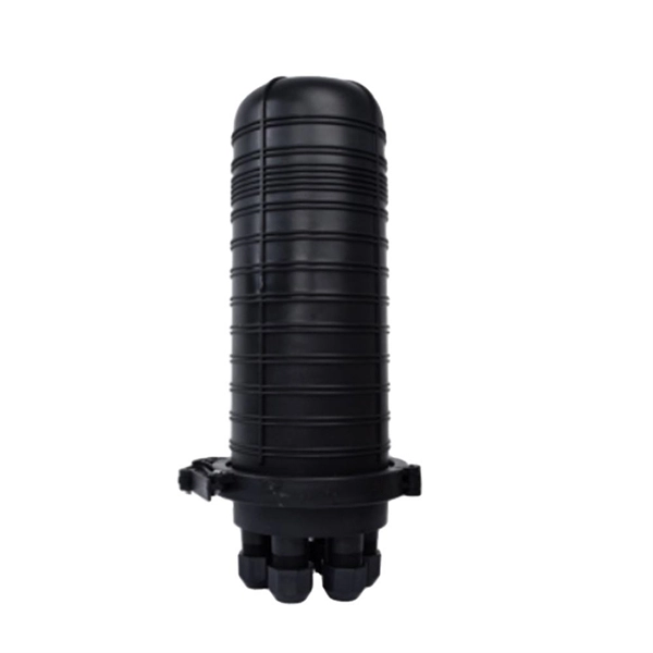
Optical cable junction boxes play a crucial role in connecting and protecting optical fibers, directly influencing the quality and lifespan of optical cable routes. Optical cable splice boxes protect the splicing parts of optical fibers from various hazards, such as water seepage due to adverse. Optical cable junction boxes play a crucial role in managing and organizing fiber optic networks. It serves as a termination point for fiber optic cables, providing protection and distribution of the optical fibers while ensuring efficient signal transmission. Utilizing an optical junction box can significantly enhance your. Optical cable splice box is a popular name, its scientific name is optical cable splicing box, also known as optical cable splicing package, optical cable splicing package and gun barrel. These boxes are designed to house and protect fiber optic splices and terminations, ensuring that the delicate fibers are safeguarded from.
[PDF]

Fiber optic terminal boxes provide functions such as input, branching and splicing of optical fiber cables. Through the connectors and splicing boxes in the terminal box, optical fibers can be quickly connected and repaired. Serving as a critical connection point, FTB facilitates the termination, splicing, or connection of fibers from various cables to other network devices such as switches, routers, or Optical Network Terminals (ONTs). It aids in splicing, splitting, storing, and managing fibers within the appropriate. The optical fiber terminal box is the terminal joint of an optical cable, one end of which is an optical cable, and the other end is a pigtail, which is equivalent to a device that splits an optical cable into a single optical fiber. A fiber pigtail is a specific hardware connection used for cable termination. It is a small enclosure that can house and protect the fiber optic cables, splices, and connectors. The optical fiber termination box and optical fiber splice box serve distinct purposes and are not interchangeable.
[PDF]
An optical power meter (OPM) is a device used to measure the power in an signal. The term usually refers to a device for testing average power in systems. Other general purpose light power measuring devices are usually called,, power meters (can be sensors or ), or lux meters. A typical optical power meter consists of a , measuring and display. The sens.
[PDF]
Fiber optic adapters play a vital role in modern optical communication systems by enabling seamless connections between fiber optic cables. These small yet essential components ensure efficient data transmission, reduce signal loss, and maintain system integrity (1). In this article, we'll explore. Explore the essentials of fiber optic adapters, their types, benefits, selection, maintenance, and their role in future tech. They serve as interfaces for connecting fiber optic cables, facilitating. Fiber optic adapters are small but essential components that ensure precise alignment between connectors. Using the wrong type or neglecting cleaning can lead to signal loss and unstable connections., two fiber connectors) such that light can reliably pass from one to the other with minimal insertion loss and maximum return loss. Though fiber optic adapters are small accessories often ignored by technicians, they play a vital role in fiber telecommunications, connecting fiber optic cables and connectors. This article discusses their purposes, features, types, and how to choose and clean them. Most fiber optic connectors are composed of.
[PDF]
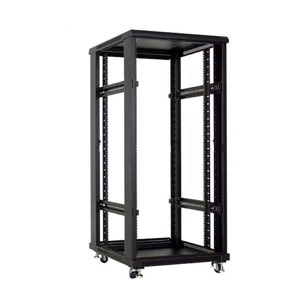
A 24-port patch panel is a networking device that allows for the organization and management of incoming and outgoing network connections. It acts as an interface between different devices such as computers, switches, and routers, allowing for easy connectivity and communication. This guide explains how to use a 24-port patch panel to manage copper and fiber cabling in a small LAN, how to choose between different patch panel types, how to design your cabinet layout, and why a patch panel is still irreplaceable in 2026. What is a Patch Panel and Why it Matters in 2026? A. Choosing a 24-port patch panel is crucial for efficiency. Learn how it enhances network capabilities. Typically, patch panels are available in a huge number of port densities from 12. In this article, we will define what a patch panel 24 port is, explain its purpose, and discuss why it is a crucial component in organising network cables. A patch panel 24 port is a device used in network cabling to connect and organise multiple network cables in one central location. It is a. Choose a 24-port patch panel when you care about clean labeling, comfortable “finger room,” and fast moves/adds/changes—especially if technicians touch the rack often and you want straightforward port-to-port mapping (Panel 01–24 ↔ Switch 01–24). Choose based on port density, cabinet space.
[PDF]

The presence of a strong sealant in the closure helps prevent water and air from entering it. Some splice closures have all cables entering into one end, usually called dome closures or sometimes called a butt closure, while some have cable entries on both ends, sometimes called inline closures. Inline closures are used in applications where two identical cables are spliced and an inline. Fiber splice joint closures are vital but often overlooked. It plays a crucial role in keeping networks running smoothly, even in the harshest conditions. Let's explore what they are, why they matter, and how technological advancements are making them even better. Fiber splice joint closures are. A fiber optic splice closure is a protective enclosure designed to house and protect fiber optic splices and, in some cases, passive optical components. It provides mechanical protection, environmental sealing, and internal fiber management for spliced optical fibers. Fiber optic splice closures have been widely used in various fields such as communication, network systems, CATV, etc. There are. CommScope addresses these challenges with a comprehensive family of fiber splice closures that prioritize essential criteria: reliability, installability, flexibility, and speed of deployment. Whether underground, aerial, or in manholes, splice closures are the first line of defense against environmental threats to your fiber.
[PDF]


