Unlike traditional metal-style reels, MARS is a lightweight, modular system constructed of an impact modified polymer that is easily transported. It is ideal for applications where cable needs to be deployed and reeled in quickly and stored efficiently. OCC's Modular Advanced Reel System (MARS ®), the industry's first lightweight cable deployment reel system, is designed specifically for the demanding needs of harsh-environment fiber optic installations. The dual take-ups are designed to work independently from line controls, therefore providing an easy adaptation and a fast plug & play installation to any line.
[PDF]

Porsche is improving the digital experience for the model year 2026 911, Taycan, Panamera and Cayenne model series. The revised Porsche Communication Management (PCM) system features more performance and offers access to the Porsche App Center. Communication Power System by Application (Wireless Access Network Base Station, Renewable Energy System, Internet Data Center, Core Network Center Room, Others), by Types (DC Power Supply, AC Power Supply), by North America (United States, Canada, Mexico), by South America (Brazil, Argentina, Rest. Tokyo – January 23, 2026 – NEC Corporation (NEC; TSE: 6701) today announced the development of a new Radio Unit (RU) for 5G Sub-6GHz band base stations, featuring Massive MIMO (*1) technology. You can find EDB at www. CPI is looking for passionate individuals to help shape the future through innovation and discovery. Job Opportunities » © 2026. In 2026, one theme is becoming increasingly clear: wireless power is evolving from a convenience feature into a foundational infrastructure layer for connected devices. What began as a wireless charging alternative is now shaping device architecture, user experience, and ecosystem design across.
[PDF]

Use this cable tray sizing calculator to check fill %, select tray size, and comply with IEC 61537 & NEC 392 with formulas, example and checklist. Our free calculator helps you determine the correct tray size based on NEC and IEC standards. Follow these simple steps: Define Tray Dimensions: Enter the width and depth of your planned cable tray (in mm or inches). Select Fill Standard: Choose 40% for power cables (NEC compliant) or 50% for. The right cable tray sizing calculator helps engineers turn cable schedules into a verified tray width and fill check before material ordering and site installation. IEC 61537 covers cable tray and cable ladder systems for the support and accommodation of cables, while NEC Article 392 governs cable. Calculate cable tray fill ratio, weight loading, and derating factors for multi-standard compliance. This calculator features an interactive interface with advanced visualizations. Open the full calculator for the best experience. Save your cable tray sizing calculator results as branded PDF. Size conductors installed in cable tray with NEC 392, NEC 310. 16, tray fill, ampacity adjustment, voltage-drop checks, grounding, and IEC design cross-checks. How to find. A 12 in ladder tray loaded to 4 in depth has 48 sq in of tray area; with 24 #12 THHN conductors at 0. 0133 sq in each, the screen is about 0. This page is a preliminary cable-tray occupancy screen for early layout work. It adds cable planning area, compares.
[PDF]

Cable tray support quantity can be calculated using a simple formula: Support Quantity = Total Length ÷ Support Spacing + 1 20 ÷ 2 + 1 = 11 supports In a typical project, a 20-meter cable tray with 2-meter spacing requires 11 supports. This article explains the principles, methods, and practical examples for calculating cable tray support quantity. Ensure NEC compliance, estimate wire length/weight, calculate deflection, and generate hardware BOMs for bends, tees, and reducers. Ideal for electrical contractors and engineers. The. This guide provides a comprehensive approach to calculating cable tray loads, considering various factors such as cable weight, tray weight, environmental influences, and safety factors. Classification of Loads Cable tray loads can be classified into the following categories: Dead Load (G): This. This page also guides to determine the appropriate distance between supports for the load, based on number of cables, cable tray size, and bracket type. Wire Mesh Cable Tray Fill Ratio = Cross section of cable / Cross section of tray According to NEC 392. 9 (B), when using ventilated tray with multi. The National Electrical Code (NEC) covers many aspects of cable tray supports and fittings. The National Electrical Code is a set of principles designed to promote public safety and welfare, as well as safeguard public health by regulating the design and operation of electrical facilities and.
[PDF]

It's called a breaker box, and even though it might not look very exciting on the outside, what's behind that little door is the heart of your home's electrical system. Bottom Line Up Front: Your home's distribution box (electrical panel) is typically located in the basement, garage, utility room, or mounted outside near your electrical meter. To find it quickly, look for a rectangular gray metal box about the size of a medicine cabinet, often positioned close to. Electrical panel boxes, aka breaker boxes, can be on a wall in an out-of-the-way area of your home. You can find electric panels inside cabinets, behind refrigerators, or inside clothes closets in older homes. Current National Electrical Codes (NEC) allow none of these locations. Electrical panels. The electrical panel is the central hub that distributes electricity throughout the house. Knowing where to find your electrical panel in your home helps in case of emergencies and routine maintenance. Panels are commonly found in garages, basements, utility rooms, and outdoor walls. Understanding how your electrical panel works can help you troubleshoot issues, perform basic maintenance, and know when to. When something electrical goes wrong in your home—like a tripped circuit or sudden power outage in one part of the house—most people instinctively head to that gray metal panel, often hidden in a basement, utility closet, or garage. Having the breaker box.
[PDF]

In this video, we'll walk you through the process of wiring a home distribution box with a detailed connection diagram. Whether you're an electrician or a DIY enthusiast, this guide will help you understand the basics of home electrical distribution. more Welcome to our. Material preparation: Prepare the required circuit breakers, wires, wiring ties and other materials, and ensure that they meet the design drawings and installation requirements. Location determination: Determine the installation position of the circuit breaker according to the position of the. An electrical panel box, also known as a breaker box or a distribution board, is a crucial component of any electrical system. It serves as a central hub for distributing electricity throughout a building, ensuring that power is delivered safely and efficiently to all the required locations. What is Distribution Board? Distribution board. A distribution board (also known as a service panel or breaker box) is a centralized collection of circuit breakers, fuses, and/or relays used to control and protect the wiring in a home. The diagram of the distribution board's wiring shows exactly how each circuit is wired and connected.
[PDF]

Main cost drivers include cable grade (indoor vs outdoor, armoured), distance, and labor for trenching, splicing, and termination. This guide presents ranges in USD and practical price estimates to help budget planning. Indoor OM3/OM4 vs outdoor armoured increases price. This guide outlines the major factors that influence fiber optic cable costs and provides practical tips for estimating pricing in bulk or project-based scenarios. Content 1 What's the Typical Price Range? 2 1. Fiber Count and Cable Construction 3 2. Fiber. Fiber-optic cable materials typically cost $1 to $6 per linear foot, depending on fiber count and cable type. Commercial building installations with 100-200 network drops generally range from $15,000 to $30,000. Single-mode fiber costs less per foot than multimode fiber, but it requires more. Buyers typically pay for fiber optic cable by length, fiber type, and installation complexity. Data aggregated from Q1 2026 contractor invoices across Texas, Ohio, and North Carolina. Cost per foot of fiber. Typically, per drop fiber cabling prices range from $250 – $1000 per drop depending on the type of fiber (OM2, OM3, OM4, or OM5), multi or single mode, PVC or plenum, average drop length, and also the number of fibers in each cable. Adding switches, high-end enclosures and other issues can also.
[PDF]
A simple rule is that each device needs two cores—one for sending and one for receiving data. Start by counting how many devices you're connecting. For example, if you have 10 devices, you'll need at least 20 cores. The total number of cores for a 1pc fiber patch cable is calculated as the number of branches multiplied by the number of cores per branch (if there are no branches, the number of branches = 1). For example, the total number of cores in an MTP®-8 trunk cable equals 4 (number of branches) x 8 (MTP-8. The number of optical cores in an optical fiber is the total number of equipment interfaces multiplied by 2, plus 10% to 20% of the spare quantity, and if the communication mode of the equipment has serial communication and equipment multiplexing, you can reduce the number of cores. The number of. One key factor is the number of cores, which impacts how much data you can transmit. This post will guide you through understanding fiber optic cores and selecting the perfect cable for your needs. Understanding Fiber Cores: Core: The central glass fiber that transmits light signals. For example, an MTP®-8 trunk cable with four branches and eight. Tip: Round counts to the connector pack before you buy. Tip: Keep one spare block for moves, adds, and changes. To calculate teh total number of fiber strands that will be.
[PDF]

A junction box contains four trade size 3 raceways: two on the left side, one on the right side, and one on the bottom. Once conductors have to turn, be pulled through, or be spliced inside an enclosure, the box dimensions start affecting installation time, conductor damage risk, and inspection results. A raceway design that looks fine in a panel schedule can still become a problem if the box is too short for an. Pull boxes, junction boxes, and conduit bodies must be sized to allow conductors 4 AWG and larger to be installed without damage to the conductor insulation. The NEC provides sizing requirements in 314. The distance between raceway entries enclosing the same conductor must be at least 6 times the trade. To size a junction box correctly, first decide whether NEC 314. Use box-fill rules for splices and devices, and pull-box rules for large conductors and raceways. The most common mistake is using the wrong. NEC 314. 28 specifies the minimum size requirements for pull and junction boxes in electrical installations. Proper sizing ensures conductors can be installed without damage and allows for proper bending space. How Does the Calculator Work? The calculator uses NEC 314. Minimum Length = 8 × Largest Conduit Size Minimum Dimension = 6 × Largest +.
[PDF]
The Aggregation Switch has a 160 Gb/s switching capacity with a 119. 04 Mpps forwarding rate, features steel construction with a fanless design, and can be rack mounted using the included kit. An Aggregation or "Top-of-Rack" switch is designed to connect everything in a rack at high speeds, then have an even bigger pipe out to the rest of the network. Power Consumption A 32-port, Layer 3 switch made for high-capacity 10G SFP+ and 25G SFP28 connections. The three layers of a traditional three-layer network design are the core layer, aggregation layer, and access layer. As the physical part of the aggregation layer, aggregation switches typically play a. IEEE 802. 3ad link aggregation enables you to group Ethernet interfaces to form a single link layer interface, also known as a link aggregation group (LAG) or bundle. The LAG balances. What is an Aggregate Switch? Understanding Centralized Network Management An aggregate switch is a high-capacity network switch that consolidates connections from multiple access switches, acting as a central point for managing network traffic and providing enhanced bandwidth capabilities. It is. Switch aggregation, also known as link aggregation or trunking, is a method used in computer networking to combine (aggregate) multiple network connections in parallel. This arrangement increases throughput beyond what a single relationship could sustain, offers redundancy in case one of the links.
[PDF]

This Quick Reference Guide is intended to provide highlights of OPGW installation instructions needed in the field. Please review the document (WI-0298 Rev 1) before proceeding with. Describe the system used for installation and delivery of OPGW fibre optic cables. - SCOPE This document covers all the activities usually performed by PRYSMIAN for on-site installation of OPGW fibre optic cables, including transport, installation, accessory assembly, verification of optical. This manual is formulated in accordance with IEEE 1138 - 2008 and IEEE 524 - 1992, etc. OPGW has dual functions of aerial ground wire and fiber communication. To. The OPGW cable installation process 2 involves careful preparation, precise laying and stringing, installation of necessary hardware, and thorough testing. I have seen that following these steps makes the installation work well and ensures high performance and reliability. I once worked on a. Discover the perfect fiber training course for your career path. This fiber optic training course is designed for those who specify, design, install, construct or maintain aerial Optical Power Ground wire systems in investor-owned, Electric Power Utilities, REAs, Co-operatives, and municipal power. Optical Ground Wire (OPGW) is a crucial component for reliable communication in power transmission systems. OPGW fiber optic cable is a unique type of cable that.
[PDF]

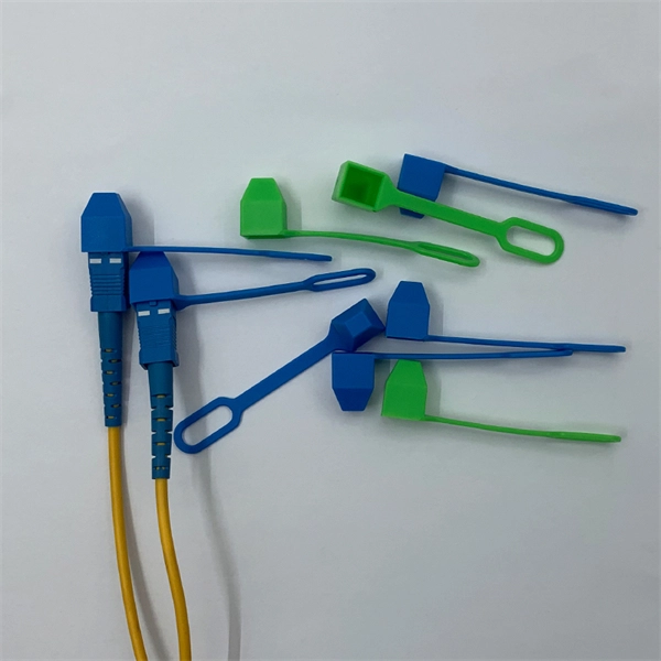
Read on to learn how a systematic approach can streamline the process, mitigate risks, and elevate overall performance in telecommunications carriers. Fiber optic cables form the backbone of modern data transmission in telecommunications. Cable identification stands as a critical practice in fiber optic networks. Misidentification can cause downtime, disrupt essential services, and create safety hazards in data centers. Industry standards like TIA-606-B guide professionals to use color codes, print legends, connector types, and. Fiber Optic Cable Tags are the perfect choice for marking your ground level and underground cables. Custom Fiber Optic Tags available upon request. Sold in package of 50 (nylon ties sold separately). Online shipping rates and pricing may differ. Indoor & outdoor fiber cable high visibility markers, id labels, printers, warning signs & posts, cable id sleeves and more for fiber optic applications. Need help? Explore write-on fiber optic cable tags with self-laminating protection. Keep your cables organized and clearly labeled with writable identification solutions. Cable Tags (Cable ID Tags, Fiber ID Tags) simplify wire and cable identification! Cable Tags (Cable ID Tags, Fiber ID Tags) simplify wire and cable identification! Fiber Tag Generic (No Company name) 4 Inches long fits 1/2" to 1" line. They are responsible for carrying vast amounts of.
[PDF]

Abstract:The design, installation, and protection of wire and cable systems in substations are covered in this guide, with the objective of minimizing cable failures and their consequences. In modern electrical systems, cable distribution boxes (also known as electrical distribution boxes or distribution boxes) play a crucial role as the key hub for managing, distributing, and protecting circuits. Whether it is residential buildings, commercial facilities or industrial sites, the. The power demanded in electricity systems also determines the cable cross-section and properties as well as the current to be transferred. In case of high power use, to meet the demand of currentAnd in order for the current to be carried at the demanded high powers to be met, the method of parallel. A distribution box is the heart of any electrical system. It takes the incoming power and safely distributes it to different circuits throughout your building. Whether in a home or an industrial facility, this box keeps your electrical setup organized, functional, and efficient. However, the key to. Distribution Board or DB is an electricity supply system or a common enclosure that distributes the electrical power feed into subcircuits. Armored Cable (Type AC). Armored cable is an assembly of insulated conductors, 14 AWG through 1 WG, wrapped with waxed paper. The conductors are contained within a fl exible spiral metal (steel or al minum) sheath that the edges.
[PDF]
