
In this guide, learn the basics of reading and interpreting electrical wiring diagrams. Follow Along on SkillCat: "Wiring Diagrams" Course! Want to test your knowledge? Skip to the quiz!. In this article, you'll learn how to read, understand and use a wiring diagram. An electrical wiring diagram could be a single page schematic of how a ceiling fan should be connected to the power source and its remote switches. A wiring diagram may include the wirings of a vehicle. For example, how. Electrical wiring diagrams are an essential tool for electricians, engineers, and automation technicians. Proper interpretation is crucial for understanding the operation of devices, diagnosing faults, and working safely with electrical installations. Understanding how to read electrical diagrams. In order to trace control system problems to the core, the ability to read and interpret various resources, from facility-level diagrams to machine-level wiring layouts, is critical. The engineering world is crammed full of drawings and diagrams of every possible kind. It shields sensitive equipment from dust, moisture, and. After reading and studying this handbook, electricians (or would-be electricians) will have a firm grasp on the many symbols used in electrical diagrams.
[PDF]

Welcome to our channel! In this video, we'll walk you through the process of wiring a home distribution box with a detailed connection diagram. What is Distribution Board? Distribution board. These smaller breaker panels, also known as sub-distribution boards, are commonly used to provide power to secondary circuits within a building. Understanding the components and wiring configuration of an electrical sub panel is essential for safe and efficient electrical installations. In this. Primary distribution systems consist of feeders that deliver power from distribution substations to distribution transformers. A feeder usually begins with a feeder breaker at the distribution substation. Many feeders leave substation in a concrete ducts and are routed to a nearby pole. This breaker must be compatible with both your main system and the additional connections. Typically, a 60-amp or 100-amp breaker will be suitable, depending on the load requirements. It includes isolator, RCCB (Residual current circuit breaker) or RCD (Residual-current device) devices, protective fuses or MCB's (Miniature Circuit Breaker).
[PDF]

We'll explain what they are, the different panel types you'll encounter, NEC 408 requirements that govern their installation, and common applications for each type. Distribution panels, breaker panels, load center, and/or distribution boards—any name you call them, they're a key part of every electrical system. Wiring distribution panels serve as the central hub and nerve center, routing power from the main service feed to multiple circuits. When setting up. In the world of electrical installations, the term DB box —short for Distribution Board box —refers to the central unit that distributes incoming electrical power to multiple outgoing circuits in a building. Whether you're powering up a residential home, a commercial office, or an industrial plant. Electrical Wiring is a process of connecting cables and wires to the related devices such as fuse, switches, sockets, lights, fans etc. to the main distribution board is a specific structure to the utility pole for continues power supply. It receives power from the main electrical supply and divides it into separate circuits, each. A distribution box, or DB box, is a circuit breaker enclosure. It is a vital part and central hub of any electrical system. It is for the economical use of wiring conductors inside, and outside of a room or building with better load control. Cleat Electrical wiring 2.
[PDF]

This guide explains how to wire a push button switch in a practical way. It covers NO vs NC, what COM does, how a 5-pin LED push button switch is typically arranged, and the most common wiring scenarios. Step-by-step push button switch wiring and installation guide with diagrams, safety tips, and troubleshooting for reliable setup. If you are a DIY builder, installer, or entry-level buyer, this is the wiring logic you can. Wiring a push button switch may seem like a daunting task, but with the right tools and a little bit of knowledge, it can be a simple and straightforward process. It is necessary to understand the steps for wiring these buttons because the right wiring gives you better results and saves you from any harm. In this blog, you will get complete guidance on wiring a push. Hey, in this article we are going to see the Single Phase Distribution Box Wiring Diagram and Connection Procedure. A distribution board or distribution box is where the main power supply is distributed to multiple loads. The main components of a push button switch are the button itself, which is usually made of plastic or metal, and the switch mechanism, which is responsible for.
[PDF]

Welcome to our channel! In this video, we'll walk you through the process of wiring a home distribution box with a detailed connection diagram. more Welcome to our. A distribution box is the heart of any electrical system. It takes the incoming power and safely distributes it to different circuits throughout your building. Whether in a home or an industrial facility, this box keeps your electrical setup organized, functional, and efficient. It serves as a central hub for distributing electricity throughout a building, ensuring that power is delivered safely and efficiently to all the required locations. What is Distribution Board? Distribution board. A distribution board (also known as a service panel or breaker box) is a centralized collection of circuit breakers, fuses, and/or relays used to control and protect the wiring in a home. The diagram of the distribution board's wiring shows exactly how each circuit is wired and connected. It also. Understanding how to safely set up the main connections of a home's power distribution system is essential for ensuring reliable and secure operation. A correct installation process minimizes the risk of electrical faults and increases the longevity of your setup. Proper knowledge is crucial for.
[PDF]

There are two electrical terminals, X and Y, where your cables must be connected. In this case, X refers to Black while Y refers to White. You need to connect X and Y with hot and neutral wires respectively. This is the most essential step. Each hot wire is 120 to 240 volts from the. Fortunately, anyone that understands color codes and electrical wiring, in general, can use X and Y wires and terminals. Circuits typically run on three wires. The hot wire brings power from the panel. In a standard setup, X and Y terminals typically correspond to specific colors: black for X and red for Y in 240V systems. Knowing these codes helps you properly connect circuits, ensuring. The standard electrical wire color code mandated by the National Electrical Code (NEC) is a critical safety system for licensed electricians. For typical building AC circuits (commonly up to 600 volts nominal), the NEC specifies identification rules for grounded conductors (neutral), requirements. Wires in electrical typically have color-coded labels., the National Electrical Code (NEC) defines required colors for neutral and grounding conductors, while hot wire colors often follow industry convention rather than strict rules. The table below gives a quick snapshot of the most common electrical wire colors you can see at home.
[PDF]

User manuals, H3C Power Supply Operating guides and Service manuals. The router supports DC, AC, and high-voltage DC (HVDC) power inputs. The power supply system is composed of power trays and power supplies. Do not install. Page 1 PSE2500-A3 External PoE Power System User Manual Hangzhou Huawei-3Com Technology Co. com Manual Version: V1. Page 2, Neocean,, TOP G, SecEngine, SecPath, COMWARE, VVG, V2G, VnG, PSPT, NetPilot, and XGbus are trademarks of Hangzhou Huawei-3Com Technology. H3C RPS800-A is an external DC power supply that provides redundant backup power for various H3C switch and router models. It supports cold backup and can seamlessly take over power supply within 2ms in case of a power supply failure in the powered device. The RPS800-A offers flexible DC outputs. The PSR150-A1 is an AC-input and DC-output power module. Both power modules provide an output voltage of 12 V and a maximum output of 150 Provide output overvoltage, short-circuit, overcurrent, and overtemperature protections. Table3-1 describes the PSR2400-54D DC power supply specifications. · Make sure the total.
[PDF]

This guide, provided by Fibconet, delves into the structure and working principle of fiber optic connectors and outlines the critical steps for creating a successful connection. Understanding Fiber Optic Connector Structure. How To Install Fiber Optic Cable Connectors? There are many types of fiber optic connectors, including SC, LC, FC, ST, D4, MU, MT/MPO, etc. These connectors can be divided into single-mode and multi-mode fiber optic connectors according to their structure and purpose. To learn more about the types. This tab provides a brief explanation of how we determine several key specifications for our 1x2 couplers. 1x2 couplers are manufactured using the same process as our 2x2 fiber optic couplers, except the second input port is internally terminated using a proprietary method that minimizes back. Fiber optic adapters, also known as couplers, play a crucial role in fiber optic networks by providing a connection point between two fiber optic connectors. In this tutorial. Fiber Optic Transceivers: For converting signals between optical and electrical form. Cleaver: For precisely cutting the fibers. Safety Equipment: Gloves. Starting with site surveys and permissions, to installing fiber optic cable and emphasizing the process as a key stage in mastering fiber optic installation, to the careful handling of cables and high-stakes splicing, each stage is critical.
[PDF]

Welcome to our channel! In this video, we'll walk you through the process of wiring a home distribution box with a detailed connection diagram. A distribution board (also known as a service panel or breaker box) is a centralized collection of circuit breakers, fuses, and/or relays used to control and protect the wiring in a home. The diagram. Do you worry about faulty wiring causing a fire in your home? Messy distribution boxes are dangerous and very hard to fix. This guide shows you how to organize circuit breaker wiring properly. You will learn to build a safe, efficient, and professional electrical system today. 2 kV on the primary side and step it down to 120V single-phase and 120/240V split-phase for residential applications. The primary side of the distribution transformer is supplied by two conductors. Wiring a Distribution Board is vital in any electrical installation. All the electrical sub circuits are originated from a Distribution Board. The Main feeder cable to the Distribution Board should be able to handle the total power anticipated when all the sub circuits in the Distribution Board.
[PDF]

Splice Diagrams or Matrices capture an electric or optical network inside a location – documenting cables, ported equipment, and connections. Splices are fiber-to-fiber, port-to-fiber and port-to-port. Fiber optic cable splicing involves joining two fiber optic cables together. Another method of connecting optical fibers is termination or connectorization, which consists of processing the end of a fiber optic bundle so that it can be connected to other fibers or devices through fiber optic. In this guide, we cover the basics of fiber optic splicing, how to perform splicing using two different methods, and finally some best practices to perform good fiber splicing. Ensure Your Splicing Tools are Clean – #2. Use and Maintain Your. What to show on a network diagram? Fiber optic network diagrams represent the architecture and connectivity of fiber optic systems, and their design philosophy integrates technical, functional, and conceptual aspects. The diagrams abstract complex details of fiber optic systems to make them. This Geoschematics drawing remains easy to read despite containing more than 2000 fibers and 500 splices. All students and instructors must wear safety glasses in this lab. It is copyrighted by the FOA and may not be distributed without FOA permission. This VHO covers similar material to the videos on YouTube. The lab manual has several.
[PDF]

This AutoCAD DWG file includes a complete Single Line Diagram (SLD) of a Distribution Board, showing circuit breakers, wiring connections, and load distribution for lighting, power, and mechanical systems. An electrical panel box, also known as a breaker box or a distribution board, is a crucial component of any electrical system. It serves as a central hub for distributing electricity throughout a building, ensuring that power is delivered safely and efficiently to all the required locations. Whether you're an electrician or a DIY enthusiast, this guide will help you understand the basics of home electrical distribution. What is Distribution Board? Distribution board. Welcome to our channel @Electricalgenius In this video, we'll take you through a detailed step-by-step guide on wiring a home distribution DB (Distribution Board) box. A distribution board (also known as a service panel or breaker box) is a centralized collection of circuit breakers, fuses, and/or relays used to control and protect the wiring in a home. The diagram. To understand how a breaker box works, it is helpful to have a wiring diagram that shows the connections between the various components. At the heart of a breaker box is the main breaker, which controls the flow of electricity from the utility into the building. This breaker is connected to a.
[PDF]
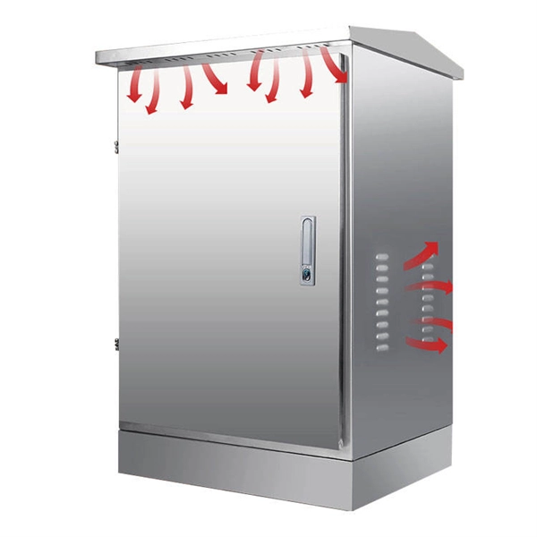
However, by using heat shrink tubing, it's possible to establish a tight, reliable seal around cables and wires, essentially providing a waterproof finish. This helps deter the risk of water-induced damage, helping to extend the durability and lifespan of your electrical systems. Outdoor junction boxes are exposed to harsh environmental conditions, including rain, snow, UV radiation, and fluctuating temperatures. Without proper weatherproofing, moisture can penetrate the enclosure through cable entries, mounting holes, or compromised seals. The consequences of poor. Heat shrink tubing is commonly used for waterproofing electrical connections, particularly in applications where exposure to moisture is a concern. Here's how waterproofing through heat shrink works: Selecting the Right Tubing: Choose heat shrink tubing that is specifically designed for. Heat shrink tubing is an indispensable thermoplastic sleeve used in wiring and cable management. It is a “must-have” insulating tool for electricians and engineers, providing reliable protection and a secure seal around wires and connectors. The outer layer is typically made of a durable, flexible polymer material (often polyolefin), which is designed to shrink when exposed to heat. This simple technology typically involves a polyolefin sleeve that has been expanded and then set with a memory to shrink back to its original, smaller size when.
[PDF]

Circuit breaker wiring configurations involve organizing main switches, busbars, and branch breakers within a distribution box. Proper setups ensure balanced electrical loads, ground fault protection, and easy maintenance. Messy distribution boxes are dangerous and very hard to fix. This guide shows you how to organize circuit breaker wiring properly. You will learn to build a safe, efficient, and professional electrical system today. Location determination: Determine the installation position of the circuit breaker according to the position of the. The distribution board is the heart of every electrical installation. This guide covers split load vs dual RCD vs RCBO board configurations, circuit arrangement and allocation, BS 7671 labelling requirements, type testing under BS EN 61439, SPD installation, wiring best practice, and the common. Distribution panels, breaker panels, load center, and/or distribution boards—any name you call them, they're a key part of every electrical system. Wiring distribution panels serve as the central hub and nerve center, routing power from the main service feed to multiple circuits. When setting up. Hey, in this article we are going to see the Single Phase Distribution Box Wiring Diagram and Connection Procedure. It serves as a central hub for distributing electricity throughout a building, ensuring that power is delivered safely and efficiently to all the required locations.
[PDF]