
As light in fibers often does not have a well defined polarization state, it is important that a fiber-optic attenuator exhibits only a minimum amount of polarization dependence. Generally, the obtained insertion loss has some dependence on the optical wavelength. Some attenuators have a relatively strong wavelength dependence and are made for working in narrow wavelength regions, e.g. with a bandwidth of only 20 nm around a center wavelength of 1550 nm. Others are optimized for a weaker wavelength dependence, making them u. For single-mode devices, the insertion loss can not depend on the direction of propagation, as long as no non-reciprocal parts are used, as e.g. in a Faraday isolator. For multimode devices, however, some loss difference is possible in conjunction with a mode dependence. For many applications, it will not be a problem if the obtained insertion loss slightly deviates from the specification (e.g. by 1 dB), or if it slightly changes over time. Example cases, however, one may require a higher precision. Most fiber-optic attenuators exhibit a relatively high return loss (at least several dozens of decibels), i.e., there is not much light which is reflected back into the input fiber. For some sensitive applications, e.g. when using an attenuator before or after a high-gain fiber amplifier, one may have two use attenuators with particularly high retu.
[PDF]

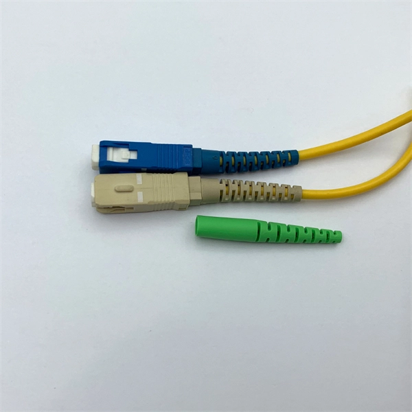
Instead of being hardwired to accept only one type of cable, an SFP+ port accepts small, hot-swappable modules—called transceivers—that you simply slide in and click into place. Need a fiber connection? Pop in a fiber module. Prefer copper? There's a module for that too. A fiber optic transceiver (also called an optical transceiver) is a compact module that both transmits and receives data signals through optical fibers. It serves a dual purpose — transmitting electrical signals as light pulses and receiving light pulses to convert them back into electrical form. An SFP transceiver acts as a compact, hot-swappable optical transceiver that. When building or upgrading a network, many IT managers focus on switches, routers, and access points—while overlooking one critical piece of the puzzle: the optical transceiver. These small modules determine how your uplinks operate: the speed, the distance supported, and whether your Cisco or. Fiber optic cabling is an alternative to copper cabling for data transmission. Popular options include: LC: Common on SFP, SFP+, XFP, QSFP, and SFF transceivers. ST, MT-RJ, and MPO: A bit less common but still in use.
[PDF]

Choosing the right fiber optic cable factory is vital to ensuring the performance, longevity, and reliability of your network. This article provides a guide from various dimensions on how to choose the right suppliers and manufacturers, along with a detailed. Selecting the right fiber optic cable manufacturer directly impacts your network's reliability, performance, and total cost of ownership. With the global fiber optic cable market valued at $13. 92 billion and growing at 10. The industry landscape features both global. This article highlights leading fiber optic cable manufacturers in the United States, renowned for their high-quality products and innovative solutions. For procurement managers and network engineers, the challenge is balancing performance, budget, and lead times. But if you want to find the best one, it's a bit difficult. Don't worry, Gcabling will help you. Gcabling, as a leading optical cable manufacturer that can. Based on 2025 rankings from industry sources like Owire and TSCables, the top manufacturers are evaluated on market share, innovation, and global reach. This list incorporates leading players, including Dekam-Fiber, Corning, Prysmian, and CommMesh, which stand out for their contributions to.
[PDF]

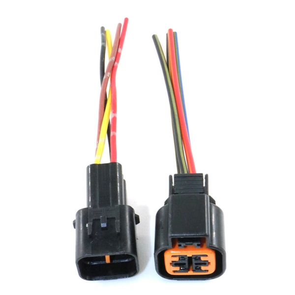
BiDi SFP+ changes the geometry: each module uses a single fiber pair directionally separated by wavelength, so you can run one strand where you previously needed two. One of the most common decisions network engineers face is selecting between single fiber SFP and dual fiber SFP modules. This comprehensive guide explores the differences between single and dual fiber SFPs, their respective benefits, limitations, and use cases—helping you make an informed choice. A single fiber SFP, also known as a BiDi SFP, is designed precisely for this purpose—enabling bidirectional data transmission over a single strand of optical fiber. Unlike traditional SFP transceivers that require two fibers—one for transmitting and one for receiving—a single fiber SFP uses. SFP (Small Form-factor Pluggable) is a compact, hot-pluggable network interface module used to connect network devices (switches, routers, firewalls) to fiber optic or copper cables. An SFP interface on networking hardware is a modular slot for a media-specific transceiver, such as for a fiber-optic cable or a copper. Both transmitting and receiving need one optical fiber to connect. Simplex SFP modules, also known as BIDI transceiver, employs a unidirectional transmission mechanism and have only one port. In practice, that means fewer splice points, smaller patch panels, and less conduit congestion—especially in retrofit buildings.
[PDF]
Optical Fiber Cable & Accessories Price in Nepal, Kathmandu. Buy with best and reasonable price @ ITShop Nepal. Nepal - Shop for Best Online at Daraz. np Wide Variety of fiber optic box. Great Prices, Even Better Service. Made of brand new materials, sturdy and durable, resistant to impact, corrosion, sealed and waterproof, safe and worry free Engineered for outdoor use, this junction box showcases a robust waterproof design, safeguarding critical fiber optic connections against harsh weather and ensuring reliable. Optical Fiber Cable & Accessories Price in Nepal, Kathmandu. SÜRGÜLÜ PATCHPANEL SC UPC DUBLEX 24XADAPTÖR 48XPIGTAIL RAL7035 1u 19” MEK. GJS-901-2 fiber optic splice closures (FOSC) are used to distribute, splice, and store the outdoor optical cables which enter and exit from the ends of the closure. There are two connection ways: direct connection and splitting connection. Applicable to situations such as overhead, man-well of. vianet: Vianet Communication Ltd. is a leading Internet & TV service provider in Nepal. Since 24 years, Vianet Communication has always remained at the forefront, providing reliable and affordable Fiber Broadband Internet Services.
[PDF]
When you see “PON” on your router, it stands for Passive Optical Network. This light indicates the status of your fiber connection to the network. Passive optical networking (PON), like active optical networking, uses fiber-optic cabling to provide Ethernet connectivity from a main data source to endpoints. While there are many subtle differences, a clear distinction between active optical networking and PON topology is PON's use of a. A passive optical network (PON) is a fiber-optic telecommunications network that uses only unpowered devices to carry signals, as opposed to electronic equipment. In practice, PONs are typically used for the last mile between Internet service providers (ISP) and their customers. The purpose of an OLT is to control, convert signals and coordinate fiber optic service (FiOS) within a PON system. An ONT. Turn off the router and disconnect the power cord. Locate the optical network (PON) port on your router. Inspect the PON cable for make sure that it is correctly connected to the router. Instead of running a separate fiber strand to every home or office, a PON shares a single fiber using optical.
[PDF]
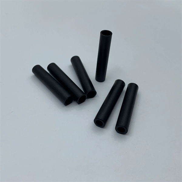
Unlike, single-mode fiber does not exhibit. This is due to the fiber having such a small cross section that only the first mode is transported. Single-mode fibers are therefore better at retaining the fidelity of each light pulse over longer distances than multi-mode fibers. For these reasons, single-mode fibers can have a higher than multi-mode fibers. Equipment for single-mod.
[PDF]

Panjiva uses over 30 international data sources to help you find qualified vendors of Ecuadorian sensors. Get access to all 13 remaining Fiber optic products suppliers with complete contact information, addresses, and business details. As of May, 2026, we have compiled data. Pricing (USD) Filter the results in the table by unit price based on your quantity. Fiber Optic Sensors are available at Mouser Electronics. Mouser offers inventory, pricing, & datasheets for Fiber Optic Sensors. How does 6Wresearch market report help businesses in making strategic decisions? 6Wresearch actively monitors the Ecuador Distributed Fiber Optic Sensor Oil & Gas Market and publishes its comprehensive annual report, highlighting emerging trends, growth drivers, revenue analysis, and forecast. These results have not been confirmed by Panjiva and are provided on an "AS IS" basis, as further described in Panjiva's Terms and Conditions of Use and Panjiva's Transparency Policy. Your use of the information provided in these results is subject in all respects to those Terms and Conditions of. Furthermore, the expansion of smart cities and the adoption of the Internet of Things (IoT) are amplifying the demand for distributed fiber optic sensors. 7 million in 2024 and is projected to grow from USD 1,581.
[PDF]

MUSCAT: The Royal Oman Police (ROP) has reported a disruption to internet services in parts of South Al Sharqiyah Governorate after fibre optic cables belonging to a telecommunications provider were accidentally cut during construction work in the Wilayat of Sur. Royal Oman Police say repair work underway; services expected to be restored within hours. ROP said in a statement: "The Royal Oman Police announces a disruption in fiber optic connections belonging to a telecommunications. Microsoft said in a status update that the Middle East "may experience increased latency due to undersea fibre cuts in the Red Sea," but gave no other details. Fibre optic cables on the ocean Floor. File pic: iStock Internet access in parts of Asia and the Middle East was disrupted after undersea. „Oman Fiber Optic always offers great service with quality product. They have very good technical sales team and logistics team and are always available for support. „ „Professional supportive sales team with excellent material quality leading to a great service!„ Technology Integration on time. Sur – Royal Oman Police (ROP) has announced a significant disruption to their digital services within the South Sharqiyah Governorate following an accidental severance of fibre optic cables. The technical failure occurred in the Wilayat of Sur, where ongoing construction activities inadvertently.
[PDF]
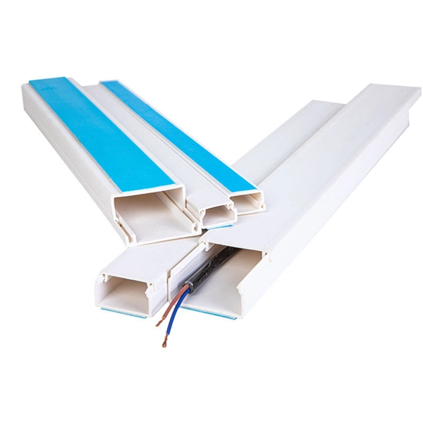
This splice case protect fiber optic cables and juction from outside plant environment damage. They are made of reinforced ABS or PC plastic, which has high strength and corrosion resistance. In addition, the splice enclosures are all hermetically sealing structure, waterproof and. Standard polycarbonate (PC) or Glassfibre reinforced (PC+GLAS) PP ABS (Acrylnitrile-butadiene -styrene) Slightly lower UV resistance compared with PC. Recommended for outdoor use if protected against weather influences GRP – GLASS FIBRE REINFORCED POLYESTER Polycarbonate and ABS enclosure materials. The fiber optic splice closure is a closed structure used for splicing, protecting and managing optical fibers. Its material selection is crucial to ensure the quality and service life of the fiber optic splice closure. These boxes are well suited as optical cable splice collection points for DAS (Distributed Antenna Systems), MTU (Multi-Tenant Unit) commercial business applications, and MDU (Multi-Dwelling Unit). It is a reentry box which is made of PC or PP material. The shells and the base are sealed with silicone gum. This product can be re-entered and used again after it is opened. Typically selected for high-density OSP splicing and branching. What is the basic structure of Fiber Optic Splice Closure? The basic structure of Fiber Optic Splice Closure includes the box body, box components, sealing ring, and lock buckle.
[PDF]

A distribution box, also known as a fiber distribution hub or optical distribution box, is a larger enclosure designed to manage and distribute fiber optic cables to multiple endpoints. It serves as a central point for connecting and organizing numerous fiber optic. Although all three are related to fiber connection and management, their installation locations, functional roles, and positions within the network architecture are fundamentally different. Confusing these devices may lead to non-standard cabling at best, and serious challenges in network. In modern FTTH (Fiber to the Home) and optical communication networks, three types of fiber distribution products are widely used: Splitter Distribution Box, ODF (Optical Distribution Frame), and Fiber Terminal Box. The functions of the four connectors can be. First, let us learn the common point among ODF, fibre optic termination box and fiber optical distribution box, actually, they have similar function, we sort out them as following 4 aspects: 1. fiber termination and optical signal splitting 4. What is the difference between these fiber boxes.
[PDF]
In a fused fiber splitter, the input fiber is aligned with the fused region, which causes the optical power to be divided between the output fibers. The tapering process gradually guides the light from the input fiber to the output fibers, resulting in a proportional split of the. A fiber-optic splitter, also known as a beam splitter, is based on a quartz substrate of an integrated waveguide optical power distribution device, similar to a coaxial cable transmission system. The optical network system uses an optical signal coupled to the branch distribution. It plays a crucial role in enabling multiple devices to share a single fiber optic connection, maximizing the utilization of the available. Essentially, a fiber optic splitter performs the following actions: Light Enters: Light travelling through a fiber optic cable enters the splitter. Passive Separation: Inside the splitter, the light is split into multiple separate beams using optical components. Conversely, it can also combine multiple signals into one. Its primary role is in Passive Optical Networks (PON), which are the foundation of. A fiber optic splitter is a passive optical component that divides a single incoming optical signal into two or more outgoing signals, or combines multiple incoming signals into one. However, modern splitters can have multiple inputs and outputs, allowing for the distribution of a single signal to dozens of receivers. The internal workings of a passive.
[PDF]

This video shows you how to build a 10Gbps fiber optic network between buildings using PoE+ switches, SFP+ transceivers, and link aggregation for even higher speeds (up to 40Gbps!). Modern network infrastructure depends on fiber aggregation switches to combine several fiber optic links into one streamlined network connection. They are built to handle large amounts of data flowing through them without interruptions over long distances. more Need to transfer. With AXIS D8308 Fiber Aggregation Switch you can connect multiple Axis devices using fiber midspans over long distances. It also enables easy expansion by simply adding more fiber or network switches. Long-distance installations often require fiber optic cables to connect different sites because of. The Cisco ASR 920 Series Aggregation Services Router is a family of fixed configuration routers that enables Service Providers to provide business, residential, and mobile access services to their users. It is the Carrier Ethernet access platform providing Ethernet services. The Cisco ASR 920. This manual provides detailed instructions for the installation, operation, and maintenance of the Ubiquiti Networks UniFi Aggregation Switch, model USW-Aggregation. Fibers in these points are either spliced.
[PDF]
