This article provides a detailed technical comparison between fiber optic and copper cables, offering a clear perspective for engineers, network architects, and procurement managers. The core distinction between the two technologies lies in the physics of data. However, the exponential growth in data demand has positioned fiber optic technology as the superior alternative for performance, scalability, and future-readiness., 10G/25G/40G/100G and beyond depending on optics and reach). Copper Ethernet scales too, but practical limits are lower and depend. The two main options are fiber optic cables and copper cables, each with its own advantages and drawbacks. Fiber optic cables are praised for their high performance and scalability, while copper cables remain a cost-effective choice, especially for budget-conscious projects and older systems. Copper wire is more susceptible to interference and has limited data capacity, making optical fiber the preferred choice for modern high-speed. Optical connectivity, utilizing fiber-optic technology, has emerged as the superior choice for modern networking, offering unparalleled performance, reliability, and scalability. For example, a typical 10 Gbps copper Ethernet link (such as Cat 6A) over 100 meters can consume approximately 5 to 8+.
[PDF]

We presented a highly efficient 1×3 optical power splitter based on photonic crystal waveguides (PCWs) with a triangular lattice of air holes. By only modifying a single hole in a Y junction area, the input power can be almost evenly split into three ports. In this paper, we present various designs of optical splitters for access networks, such as GPON and XG-PON by ITU-T with triple-play services (ie data, voice and video). The presented designs exhibit a step forward, compared to the solutions recommended by the ITU, in terms of performance in. Optical Line Terminal Equipment (OLTE), Optical Network Unit (ONU), Erbium-Doped Fiber Amplifier (EDFA), Asynchronous Digital Subscriber Line (ADSL), Very High-Speed Digital Subscriber Line (VDSL) The technical paper explains in detail about the basic design & implementation of Triple play service. A fiber optic splitter is a passive optical component that divides a single incoming optical signal into two or more outgoing signals, or combines multiple incoming signals into one. The optimal device can operate with a. To provide a unified business, we must have a network platform that can support various multimedia (streaming) business such as audio and video. The characteristics of these businesses are large business demand, large data volume, and high service quality requirements. Therefore, it is generally. problematic when the number of requests in an area with a demand that vertical building in an area.
[PDF]
QSFP-DD is a new module and cage/connector system similar to current QSFP, but with an additional row of contacts providing for an eight lane electrical interface. It is being developed by the QSFP-DD MSA as a key part of the industry's effort to enable high-speed solutions. Cisco QSFP-DD and OSFP 800G ZR/ZR+ digital coherent optics modules enable 800G traffic over amplified Dense Wavelength-Division Multiplexing (DWDM) links up to 120 km for 800ZR and over 1000 km for 800G ZR+. QSFP-DD (Quad Small Form-Factor Pluggable Double Density) transceivers double the number of high-speed electrical interfaces in QSFP to achieve 400G Ethernet speeds – and double them again to reach 800G. As a. Abstract: This specification defines: the electrical and optical connectors, electrical signals and power supplies, mechanical and thermal requirements of the pluggable QSFP Double Density (QSFP-DD) module, connector and cage system. This document provides a common specification for systems. Amphenol's QSFP-DD high-speed connector family features a scalable, high-performance interconnect platform with 76 contacts on a 0. 8mm pitch and a dual-mating interface. The QSFP-DD family supports legacy QSFP channels on the front interface and four additional channels on the rear interface. With its compact form factor, backward.
[PDF]

These core components of optical fiber communication system — transmitter, optical fiber, receiver, plus supporting elements like amplifiers and multiplexers — enable lightning-fast, interference-free communication over vast distances. Fiber optic communication refers to a method of transmitting data that utilizes light instead of electrical signals to send information through optical fibers. It works on the principle of total internal reflection, allowing light to move through the fiber with very little loss. The process kicks. In order to comprehend how fiber optic applications work, it is important to understand the components of a fiber optic link. Simplistically, there are four main components in a fiber optic link (Figure 1). These systems rely on three vital components working together – the communication channel, the optical transmitter, and the optical receiver. Optical fiber communication system 1. Encoder Encoder converts the analog information like voice, figures, objects etc into the binary data. Optical fibers are thin, flexible strands of glass or plastic that serve as the medium for transmitting light signals. Some exceptional characteristic features of this type of communication system like large bandwidth, smaller diameter, lightweight, long-distance signal.
[PDF]
GPON uses passive optical network (PON) is a access in which a single optical fiber from a central location is shared by multiple end users through one or more in series (cascaded). Unlike traditional fiber connections, PON systems distribute optical signals from an (OLT) to many (ONUs) or (ONTs) without requiring active electronic equipment in the distribution network. The absenc.
[PDF]

Optical splitters play a crucial role in Fiber to the Home (FTTH) Passive Optical Network (PON) systems, efficiently distributing a single optical signal to multiple destinations. The split ratio and insertion loss are two key parameters defining their performance. Understanding Fiber Optic Splitters: Principles, Parameters, Types, Applications, and Future Trends 1. Introduction Fiber optic splitters are integral components in the world of optical networks. A deeper understanding of these. 📄 What is an Optical Splitter? An Optical Splitter, also known as a beam splitter, is a passive optical device that divides a single input optical signal into two or more output signals. Conversely, it can also combine multiple signals into one. Its primary role is in Passive Optical Networks. Bandwidth is shared amongst customers in a PON, and the bandwidth received by a customer is not related to the power received at the optical network terminal (ONT) as long as the power is high enough so the ONT can operate. Their ability to efficiently manage optical signals makes them indispensable in various. The performance of optical beam splitters can significantly influence the overall performance of laser-based instrumentation and measurement systems. This paper examines two of the most critical performance factors: optical efficiency and wavefront distortion. Efficiency is a function of both the.
[PDF]

OSFP, or Octal Small Form-factor Pluggable, is a high-speed transceiver form factor designed for next-generation data center networking. Compared with previous generations of optical modules, OSFP is optimized for higher bandwidth, better thermal performance and denser port. Among the various 400G optical transceiver form factors, OSFP stands out as a next-generation form factor specifically designed for high-speed Ethernet, offering clear advantages. This article introduces the fundamental concept and key characteristics of 400G OSFP Ethernet optical transceivers, and. Optech, a Taiwan-based optical transceiver manufacturer, provides professional 400G OSFP and 800G OSFP solutions designed for AI, cloud, high-performance computing, data center and advanced networking applications. Understanding MSA is critical for compatibility validation, cost. As data centers transition from 400G to 800G interconnects, bandwidth demand, power efficiency, and thermal constraints have forced the industry to look beyond traditional form factors. Designed to support 400 Gigabit Ethernet transmission with improved thermal performance and higher power capacity, OSFP modules are widely adopted.
[PDF]
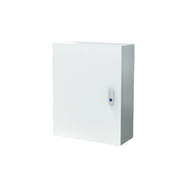
Building an Efficient Fiber Infrastructure. The ATB3120-S-8 ADU (Active Distribution Unit) is an active optical device used to connect the main FTTR and the sub FTTR. It provides optical signals and power input for the sub FTTR. The products can be installed in an indoor information box or on a. Huawei includes the HUAWEI eKit ATB3120-S-8 Optical Socket in its MiniFTTO optical access portfolio. This device works as an optical socket used in FTTR and MiniFTTO fiber distribution systems. 0 solution uses two transformative technologies to support five typical network scenarios. In the earliest FTTH solution, ODN 1. 0 optical splitting was used for. 124 Available: Delivery 2-3 Business Days The Huawei ATB3120-S-8-XC/UPC-2 ADU is a cutting-edge optical distribution unit designed to enhance network performance with precision and reliability. This advanced device provides seamless fiber optic distribution, accommodating up to eight connections.
[PDF]

ITU & IEC allow 0. 75 dB loss per mated pair. Splitter loss values are "Typical" and include a connector in and out. These values are approximate and should not be exceeded by more than 1-1. 5 dB, which could indicate dirty connectors, bad splices, or. ITU & IEC allow 0. These are known as passive optical splitters, and they perform the function. Let's start with the simplest part: the ideal, theoretical loss caused purely by dividing the light equally among N paths. This is often called Distribution Loss or Ideal Split Loss. Understanding the types of splitters, their impact on network performance, and how to measure their losses ensures high-quality network operation and facilitates optimal splitter selection based on. Use 2×N when two inputs feed the same distribution stage. Common values: 2, 4, 8, 16, 32, 64. Wavelength is recorded in outputs for documentation. 5 dB depending on splitter type. Fusion splices often plan around 0. Optional: patch. Excess loss is the ratio of the optical power launched at the input port of the splitter to the total optical power measured from all output ports. It assures that the total output is never as high as the input. Components, such as fiber cables, splitters, and switches, introduce attenuation. The maximum allowable distance between a transmitting laser and receiver is based upon.
[PDF]
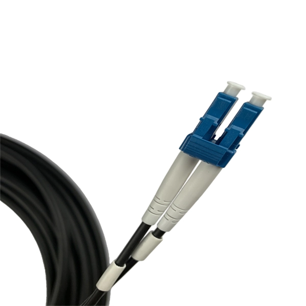
A fiber-optic cable, also known as an optical-fiber cable, is an assembly similar to an but containing one or more that are used to carry light. The optical fiber elements are typically individually coated with plastic layers and contained in a protective tube suitable for the environment where the cable is used. Different types of cable are used for in different applications, for exa.
[PDF]
Its function is to split two incident light beams from two individual input fiber cables into sixty-four light beams and transmit them through sixty-four individual output fiber cables. A fiber-optic splitter, also known as a beam splitter, is based on a quartz substrate of an integrated waveguide optical power distribution device, similar to a coaxial cable transmission system. The optical network system uses an optical signal coupled to the branch distribution. These devices are commonly used in fiber optic networks to distribute signals to various endpoints. Optical splitters work by using a branching mechanism that allows the signal to be evenly. An optical splitter is a crucial passive fiber optic device that splits and combines optical signals. It can distribute the optical energy transmitted through a single fiber to two or more fibers in a predetermined ratio or combine the optical energy from multiple fibers into one fiber. Optical splitter.
[PDF]

GrenTech specializes in the development and production of optical splitters, offering a comprehensive range of 1xN and 2xN splitter products known for their low insertion loss and compact design. A must-have gigabit upgrade for your home or office in 2025! the nocin 1x2 splitter supports sc/lc/fc interfaces, features carrier-grade tapering technology, boasts a low insertion loss of just 0. 3db, and delivers a stable transmission rate exceeding 980mbps in real-world testingSuitable for. Wuhan Wolong communication technology Co., Ltd is located at Optical Valley, Wuhan, China, with the registered capital of 5. With development for many years Wolong is now one of the professional suppliers in communication industry. We are known as high-quality products with good. Shenzhen Shengcomm Co. Their PLC fiber splitters are particularly suited for applications in FTTH, passive optical networks. Product Details: Shiningfiber is a fiber optic manufacturer and supplier in China, offering a range of products including Terminal Boxes, Fiber Splitters, SFP Transceiver Modules, Patch Cords & Pigtails, Fast Connectors, and Accessories & Tools. China Fiber Patch Cable, Fiber Optical Splitter. Since 2020 is not over yet, we have to refer to the 2019 annual corporate financial report to list the top 10 fiber optic communication brand suppliers in China: In 2019, Huawei's revenue was US$122 billion, slightly lower than Microsoft's US$125. 8 billion, making it a veritable multinational.
[PDF]

Single-mode optical splitters are optimized for single-mode optical fiber, while multimode optical splitters are tailored for use with multimode optical fiber. An Optical Splitter, also known as a beam splitter, is a passive optical device that divides a single input optical signal into two or more output signals. Conversely, it can also combine multiple signals into one. Its primary role is in Passive Optical Networks (PON), which are the foundation of. This guide demystifies fiber optic splitters, explaining their design, operating principles, types, key specifications, and real-world applications. It can distribute the optical energy transmitted through a single fiber to two or more fibers in a predetermined ratio or combine the optical energy from multiple fibers into one fiber. “Passive” means it needs no. You use optical couplers and splitters to split or join signals in fiber networks. For example, optical splitters send light to many output ports. This lets you connect more users to one network terminal. There are different types of fiber optic splitters available, with two of the most common being Fused Biconical Tapered (FBT) splitters and Planar Lightwave.
[PDF]