High-definition temperature sensing based on the natural Rayleigh backscatter in optical fiber delivers a virtually continuous line of temperature measurements with sub-millimeter spatial resolution. 1. Map temperat.
[PDF]
We describe a theoretical and experimental study of an intensity-based, dual-wavelength referenced fiber optic temperature sensor utilizing temperature-induced spectral shifts of optical thin-film interference coatings, deposited on a sensor fiber end. We present coating design considerations that. This study proposes the development of a dual-wavelength optical fiber sensor (DWOFS) that integrates two optical fiber structures in a multimode transmission line to measure the refractive index and temperature of a liquid concurrently. One structure is based on a refractive index sensor that. ter. The dual-wavelength fiber laser has a ring cavity composed of two FBGs with central wavelengths of 1550. Through monitoring the wavelength shift and the output power difference of the dual-wavelength fiber laser, the simultaneous measurement for RI and temperature is. To improve the sensitivity measurement of temperature sensors, a fiber optic temperature sensor structure based on the harmonic Vernier effect with two parallel fiber Sagnac interferometers (FSIs) is designed, and theoretical analysis and experimental testing are conducted. The FSI consisting of. Fiber-optic high-temperature sensors are gradually replacing traditional electronic sensors due to their small size, resistance to electromagnetic interference, remote detection, multiplexing, and distributed measurement advantages. This paper reviews the sensing principle, structural design, and.
[PDF]

Identify and compare relevant B2B manufacturers, suppliers and retailers. Identify and compare relevant B2B manufacturers, suppliers and retailers. Identify and compare relevant B2B manufacturers, suppliers and retailers Max. Brolis Sensor Technology specializes in advanced photonic sensor technologies, including the development of integrated optical sensors for healthcare and industrial applications. Their innovative sensors utilize. Fiber Optic Devices Ltd. (FOD), an employee owned company, is a complete fiber optic technology company offering a variety of products and services to the OEM and End-user markets. Founded in 1991, FOD is a recognized leader in partnerships in the design and manufacturing of Fiber Optic Components. Also, please take a look at the list of 38 optical sensor manufacturers and their company rankings. Here are the top-ranked optical sensor companies as of May, 2026: 1. WIN SOURCE ELECTRONICS, 2. Vishay Intertechnology, Inc. The Workshop of Photonics (WOP) specializes in femtosecond laser micromachining, providing ultra-high precision services for various materials, including glass and ceramics. Their innovative approach enhances productivity and provides critical data for improving nutrition and.
[PDF]

Get price quotes for Fiber Bragg Grating. Contact suppliers directly with one click. Use this fiber Bragg gratings buying guide to compare major types, define selection criteria, and find suppliers: Professional purchasing of high-value photonics products is a substantial responsibility, where a structured decision-making process is essential. RP Photonics offers a lot of help: Get. Comparing fiber bragg grating sensor prices. How does 6W market outlook report help businesses in making decisions? 6W monitors the market across 60+ countries Globally, publishing an annual market outlook report that analyses trends, key drivers, Size, Volume, Revenue, opportunities, and market segments. All our Fiber Bragg Grating Arrays and Cable models are designed to make handling and deployment fast, easy and intuitive. Technica. Transmission spectrum for a sample FBG with center wavelength of 1546. 83nm and 90% reflectivity: Please note: the FBG is made on bare single mode fiber and has no steel tube or any other types of package. © 2024 CB Cabling Technologies Ltd.
[PDF]

The setting value can be finely adjusted manually. Press and hold the and buttons simultaneously for three seconds. Use the to select "rSt", then press the button. Settings are summarized in "Basic" and "Advanced" categories. Providing quick solutions for every scenario. In cases where more advanced features or troubleshooting is necessary, the "Advanced". This video covers how to setup and configure the Wenglor OPT2041 Fiber Optic Sensor from AutomationDirect. **Please check our website for our most up-to-date product pricing and availability. This sensor works with both Plastic and Glass fibers. Keep in mind that the color and reflectivity of the. The KEYENCE FS-N10 Fiber Sensor is a versatile and reliable device used for detecting objects. This sensor uses a fiber optic cable to transmit and receive light, allowing for accurate and precise detection in a variety of applications. The FS-N10 series is capable of detecting objects of different. Fiber optic Sensors; How to program Keyence Fiber optics amplifier from EMI Documentation can be found here:. This is the SET push button; this is used to calibrate the sensitivity.
[PDF]

Learn how to splice fiber optic cable using fusion splicing with this complete step-by-step guide. Includes tools, best practices, loss standards (ITU-T G. 652), cost analysis, and FAQs for network engineers and installers. Splicing fiber optic cable is an extremely important phase for making dependable, high-speed communication infrastructures. Regardless of the type of fiber network you're deploying, be it for telecom, enterprise data centers, or smart city infrastructure, fusion splicing provides the benefits of. This is where fiber optic cable splicing—the process of creating a permanent, high-performance join between two fiber ends—becomes critical. For network managers and technicians, a poor splice can lead to significant signal degradation, network downtime, and costly troubleshooting. At Turn-Key. Think of a fiber optic cable splice as the seamless stitching that keeps data flowing through the delicate threads of a network—like a master tailor joining fabric with precision. What is Fiber Optic Splicing and Why is it Needed? – #1. Discover how to efficiently use sleeves and the heat. The answer lies in splicing, both fusion and mechanical. In this comprehensive guide, we will delve into when.
[PDF]

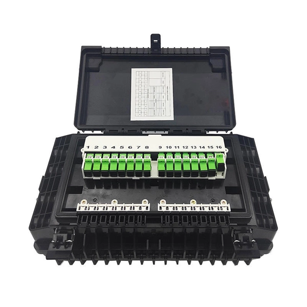
A distribution box, also known as a fiber distribution hub or optical distribution box, is a larger enclosure designed to manage and distribute fiber optic cables to multiple endpoints. It serves as a central point for connecting and organizing numerous fiber optic. Although all three are related to fiber connection and management, their installation locations, functional roles, and positions within the network architecture are fundamentally different. Confusing these devices may lead to non-standard cabling at best, and serious challenges in network. In modern FTTH (Fiber to the Home) and optical communication networks, three types of fiber distribution products are widely used: Splitter Distribution Box, ODF (Optical Distribution Frame), and Fiber Terminal Box. The functions of the four connectors can be. First, let us learn the common point among ODF, fibre optic termination box and fiber optical distribution box, actually, they have similar function, we sort out them as following 4 aspects: 1. fiber termination and optical signal splitting 4. What is the difference between these fiber boxes.
[PDF]

The fibers within a butterfly cable are housed in a tight buffer, reducing their exposure to tension and ensuring that any strain applied to the outer jacket does not translate directly to the optical fibers. The invention provides a flexible physical flame-retardant low-friction compression-resistant butterfly-shaped optical cable and a production method thereof, and relates to the field of optical cables. The optical fiber core is located in the center of the cable body, two reinforcing cores are placed on both sides, and the outer layer is enveloped and sheathed to form a cable. FTTH (Fiber to the. Fiber optic technology has revolutionized internet connectivity, and the Butterfly Fiber Optic Cable GDX702 stands at the forefront of this innovation. As fiber optic cable manufacturers continue to refine their products, understanding the technical intricacies becomes crucial for network planners. FTTH butterfly optic cables are specially engineered to facilitate high-speed internet connections directly to residential homes. Their name stems from the distinctive "butterfly" shape, which is a result of their layered construction. Its innovative design positions the communication unit at the core, flanked by two parallel non-metallic strength members (FRP) for enhanced compression resistance and.
[PDF]

Strip the cable the required length, minimum 0. 5 meter or more, to establish easy and safe installation with enough buffer size. Pass the stripped cable into the upper side of the splice tray. Fix the cable strength member (3) on part (2) and stabilize with cable fixing part. To establish easy and safe installation put the box where it will be installed and measure the required length of the cable. 5 meter or more, to. Lockable Cable inputs: 2x 12mm - 16x Space for 1x16 SC splitter or 1x32 LC splitter 1. Cable fixing Instert the stripped cable through the cable entry port and fasten the FRP element(s) to the block. The outher coating should be fasten useing the steel hops. Do not fasten too. Stripping and preparing fibre optic cables for termination is a critical step in the installation and maintenance of fibre optic networks. Firstly, it is important to consider that when stripping multi-layer cables for connectorization, each layer must usually be stripped individually, as they all usually need to be stripped to different lengths. Cutting and stripping the cable jacket can be done with a special fiber stripper or a properly set wire stripper as long as it does. Whether it is indoor or outdoor fiber-optic (FO) cable, using a step-by-step approach reduces the chance of fiber damage while ensuring the performance of fibers. In our continuing discussion of installing FO cables, let's use a step-by-step approach in detailing how to strip and clean indoor and.
[PDF]

Under the TIA/EIA-598-C standard, the universal 12-color sequence is: 1-Blue, 2-Orange, 3-Green, 4-Brown, 5-Slate (Gray), 6-White, 7-Red, 8-Black, 9-Yellow, 10-Violet, 11-Rose, and 12-Aqua. This sequence repeats for cables with more than 12 fibers. Table 151-13 uses the worst case S0 and ZDW given in Table 151-14, and calculates the worst case positive and negative dispersion using the worst case TX wavelengths given in Table 151-7 and footnote (b), and the worst case fiber length (operating distance). 3 has analyzed. The two fiber parameters that have the greatest effect in limiting digital transmission over optical waveguides are attenuation and pulse spreading. In single-mode fibers, pulse spreading is caused by chromatic dispersion. Attenuation attracted most of the attention in the early years of. *Values for cabled fibre, local attenuation discontinuity ≤0. 1dBNote: Due to OTDR measurement uncertainty B3 International cannot guarantee attenuation values at fibres shorter than 1000m. Parameters are subject to change without notice. General Symmetric cable pairs Land coaxial cable pairs Submarine cables Free space optical systems G. 649 Optical fibre cables G. @1310nm (typical/max. The tutorial has the following parts: Chromatic dispersion is the phenomenon that the phase velocity and the group velocity of light propagating in a fiber depend on the optical frequency. It is relevant for many applications.
[PDF]

An optical module sends data as light through fiber cables. Light is faster than electricity, making it great for quick communication. The optical module serves as a crucial component in optical fiber communication systems, operating at the physical layer, which is the lowest layer in the OSI model. Its primary function is to achieve optoelectronic conversion by converting electrical signals into optical signals and vice versa. This technology is crucial for fast and reliable data transfer in networks. Optical modules typically have an electrical interface on the side that connects to the inside of the system and an optical interface on the side that connects to the outside. Optical fiber transmission forms the backbone of modern high-speed communication networks, enabling the efficient transfer of massive datasets across vast distances. These modules typically consist of a transmitter, which converts electrical signals into a light signal, and a receiver, which converts the received signal back. In high-speed data networks, the seamless integration of fiber optic cables with SFP (Small Form-Factor Pluggable) modules is critical for reliable signal transmission. SFP transceivers bridge electrical and optical signals, making them indispensable in data centers, telecom networks, and.
[PDF]

If you're leading a project involving fiber—whether for a healthcare facility, retail expansion, or OEM partner network—this guide will walk you through every technical phase of planning a fiber optic installation from scratch. Before we dive in, understand this:. Building a fiber optic network is a highly technical yet vital process that enables communities and businesses to access high-speed, reliable fiber optic internet. From the initial site survey to the final fiber to the home (FTTH) connection, every stage requires careful planning, coordination, and. The Fiber Optic Association, Inc. (FOA) was founded in 1995 to help develop the workforce to build the fiber optic networks to support a rapid expansion in communications and the Internet. It includes first determining the type of communication system (s) which will be carried over the network, the geographic layout (premises, campus, outside. Optical Fiber Cable Engineering Construction: A Comprehensive Operation Guide 1. This recommended practices document is a comprehensive manual for optical fiber construction and testing. Sections are included for project management; cable handling, testing and equipment; overhead cable placement; underground cable placement; underground enclosures; bonding and grounding; cable.
[PDF]

The optical power meter is similar to the voltohmmeter in application but measures the optical resistance (losses measured in dBm or dBM) of a cable before and after installation and provides a comparative analysis of the splices. The range of the meter is adjustable. Regularly testing fiber optic cables helps minimize network downtime, lengthens the network's longevity, reduces maintenance requirements, and helps support network reconfiguration and upgrades. These factors significantly add to the fiber optic network's long-term performance, manageability, and. Several types of tests are commonly conducted to assess and maintain the health of fiber optic networks. Continuity testing verifies that the fiber is intact and that light can pass through from one end to the other without any blockages. These test procedures assess the physical and functional qualities of fiber optic cables, connectors, and the network as a whole. Key tests include: Effective fiber testing utilizes advanced tools such as Optical. One way to test a splice is to use an Optical Power Meter. As the components like fiber, connectors, splices, LED or laser sources, detectors and receivers are being developed, testing confirms their performance specifications and helps. Regular testing of fiber optic cables is not just a preventive measure; it's an investment in the longevity and efficiency of your network. By identifying potential issues early, you can enhance.
[PDF]
