Designed by engineering firm PJ Ford Engineers, 25 Oldcastle Infrastructure CELL BLOCKS were manufactured to create the 35-foot by 35-foot foundation for the major telecom carrier's wireless cell tower, mi.
[PDF]

Comprehensive Guide to Civil Construction for Telecom Tower Sites In the ever-evolving landscape of telecommunications, the construction of tower sites serves as the backbone for reliable network connectivity. A communication tower foundation design is the structural blueprint that determines the anchor point of the tower on the ground. This article delves into the intricate process of civil construction tailored. Telecom (Telecommunications) towers are a generic description of radio masts and towers built primarily to hold telecommunications antennas. As such antennas often have a large area and must be precisely pointed out, such towers have to be designed and built to limit wind induced movement. So very. With excellent resistance to axial and lateral loads in both compression and tension, they're an efficient and durable foundation that's easy to remove and remediate. Monopole towers are popular in urban areas owing to their minimal footprint and adherence to city planning. The foundation type can be either mat foundation or monopile foundation. If you're planning a new installation, knowing the basics of these foundations can help you establish a secure and durable tower that will be a community asset for years to come.
[PDF]

CT-S3T-2 tower section weight does not exceed 26 kg. Transmission tower weight per meter varies dramatically by voltage level: 35kV towers average 100-180 kg/m, 66kV systems run 150-250 kg/m, 110kV towers range 200-450 kg/m, 220kV structures reach 350-600 kg/m, and 500kV ultra-high voltage towers require 500-800 kg/m. This weight increases. Due to the complicated nature of tower infrastructure, it can prove invaluable to have an engineer approved recommendation for solutions that will accommodate your particular project. We offer a Tower Recommendation Proposal Consultation Service, providing a detailed report that you can use for the. 18m Telecom Tower Ma /www. inf. ASMTower automatically performs load calculation on telecom structures, wind load, ice load and dead load according to the following design standards: ASMTower performs wind and ice load calculations according to the chosen code and distributes the resulting loads, along with the weight of the. Get Latest Price from the seller Khan Enterprises - Offering Selp Sport Wi-Fi Tower, Size: 18 Mtr Rtt at ₹ 3500/meter in Bengaluru, Karnataka. Get WiFi Tower at lowest price | ID: 20500615430. Now, let's take a look at the pricing options: 1. Non-upgradeable: • 12 meters: R49,990. 00 ex VAT ex works PLUS R49,000. 00 ex VAT for site visit, civils, and installation.
[PDF]

Telescopic mast system with advanced vibration-dampening technology to minimize jitter and ensure stable communication and data transmission, even in the most demanding terrain and vehicle movements. Fireco designs and manufactures the most comprehensive line of standard and custom telescopic masts using high quality materials with industry leading engineering and quality testing practices to provide our customers with the world's best mobile masts. Will-Burt's telescopic masts and tower systems provide intelligent. Telescopic mast systems play a critical role in modern field operations—enabling elevation of cameras, antennas, lights, sensors, and communication gear in demanding environments. Whether for surveillance, broadcasting, defense, or emergency response, choosing the right mast system ensures reliable. Floatograph, along with its utility industry partner, Eversource Energy, developed the Rapid Pole® – Temporary Power Pole system to reduce customer downtime, allowing crews to re-energize a circuit in as little as 20 minutes. Floatograph's masts come in height options from 10 to 100 feet, and are. Advanced telescopic mast solutions designed for versatility in the field, providing crucial support for on-the-move (OTM) missions. Erecting the Telescoping Mast is made by simply connecting guys and brackets to the attached unique heavy duty rolled edge guy rings and clamps, extend the sections, insert the locking cotter pins, rotating the tubes to.
[PDF]
An optical line termination (OLT), also called an optical line terminal, is a device which serves as the service provider endpoint of a passive optical network. It provides two main functions: to perform conversion between the electrical signals used by the service provider's equipment and the fiber optic signals used by the passive optical network.to coordinate the multiplexing between the conversion. FeaturesOLTs include the following features: • A downstream frame processing means for receiving and churning an cell to generate a downstream frame, and converting a parallel dat. Most vendors integrate an entire fiber optic management system for ISPs to manage OLTs as well as client ONTs and as such are not interoperable. • • BT-PON.
[PDF]
The Open Systems Interconnection (OSI) model is a developed by the (ISO) that "provides a common basis for the coordination of standards development for the purpose of systems interconnection." In the OSI reference model, the components of a communication system are disting.
[PDF]

Urban Areas: 25–40m spacing (concrete poles, 10–12m height)., steel lattice structures). Factors: Cable weight (kg/km) Ice loading (up to 50mm. The Fiber Optic Association, Inc. (FOA) was founded in 1995 to help develop the workforce to build the fiber optic networks to support a rapid expansion in communications and the Internet. The charter of the FOA was to promote professionalism in fiber optics through education, certification, and. to n utral comm. cable R. FO-CS JOINT USE CLIMBING SPACE REQUIREMENTS 51. APPENDIX A - COVER SHEET / TOC 52. RUS DRAWING #PM12 58. CHECK. d suppliers of electrical construction services. They define a minimum baseline of quality and workmanshi for installing electrical products and systems. NEIS® are intended to be referenced in contrac documents for electrical construction ation or liability to users of this publication. Choose the type of pole The basic pole height is 7m and the tip diameter is 150mm. In case of special sections, crossing obstacles or roads or railways, the pole height of 8m, 9m, etc. can be selected. Cables 300 V or less need to be a minimum two feet over the street light. Climbing Space is an unobstructed, vertical space along the side or corner of the pole. In gen-eral, it consists of an imaginary box, 30-inches square, extending at least 40 inches above the highest communications cable or.
[PDF]
Engineered, manufactured, supported and delivered – with pride. We are a British based manufacturer of Copper Cabling Systems, Fibre Optic Products, Racks and Enclosures – deployed in Datacomms, Data Centres, FTTx & Telecom, Broadcasting and Smart Home Applications. British Cables Company is unique by any standards. Not only have we manufactured cables here in Blackley, Manchester since 1895, but also we are evolving into one of the most proficient service providers in the industry. British and proud? Absolutely! The business has always benefitted from. Alker Fibre Optics is an approved supplier direct to the UK MOD and a trusted partner for a number of specialist prime contractors within the military sector. We are always interested to work. Identify and compare relevant B2B manufacturers, suppliers and retailers Max. The company specializes in cabling and IT infrastructure services, highlighting its expertise in fiber optic cable supply and installation. With over 10 years of experience and a fully accredited team, they ensure. For 25 years Copper & Optic has been providing the highest quality electronic manufacturing services. We produce and supply cable and harness assemblies, PCB and fibre optic assemblies, potting and moulding, and automatic testing. Telecom ducting pipe is a non-flexible PVC pipe that carries telecom & data cables. Products are available for purchase online with free 30 day.
[PDF]

In this guide, we break down the two core stages of optical fiber manufacturing: preform production (shaping the precursor material) and fiber drawing (transforming the preform into thin, usable fiber). Optical fiber preforms are the starting point behind every kilometer of fiber optic cable. Though rarely seen by end users, these cylindrical glass rods serve as the base material from which high-speed optical fibers are drawn. As global communication relies more than ever on fiber networks—from. 📦 For purchasing, use the RP Photonics Buyer's Guide for fiber preforms. It provides an expert-curated supplier directory, buyer-focused technical background information, and structured selection criteria to support professional procurement decisions. During the fiber drawing process, the preform is heated and drawn into a. The production of optical fiber is a precision-driven process that transforms raw materials like silicon tetrachloride into ultra-thin, high-performance fibers capable of transmitting terabits of data over thousands of kilometers. Who invented optical fiber and when? Corning scientists Dr. Peter Schultz, and Dr.
[PDF]

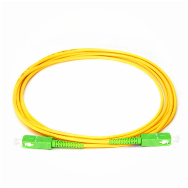
Fiber optic transmission distance varies based on fiber type, environmental conditions, and equipment selection. This guide explores the key factors affecting fiber optic transmission distance and provides practical selection guidelines for a stable and. Fiber optic cables use light to transmit data, while traditional cables, such as copper cables, use electrical signals. In fiber optic cables, data is transmitted as pulses of light that travel along a thin strand of glass or plastic fiber. The core of the fiber is made of a highly transparent. In fiber-optic communication, a single-mode optical fiber, also known as fundamental- or mono-mode, is an optical fiber designed to carry only a single mode of light - the transverse mode. Dispersion. In the complex landscape of fiber optic infrastructure, selecting the right cable type—single-mode (OS1/OS2) or multimode (OM1/OM2/OM3/OM4/OM5)—can define a network's speed, reach, and cost-effectiveness. They feature low attenuation benchmarks 2 and minimal dispersion. They use OS1 or OS2 OS1 or OS2 classifications to.
[PDF]
Because fiber optic cables don't come in one continuous length, sections must be joined together through splicing. This process fuses two glass strands so light signals can travel through them without interruption. Below is a detailed look at each step of fiber optic network construction, including key terms and methods used across the industry. Engineers and. We are experts in the installation and use of fiber optic cable to residences, apartment buildings, businesses and cell sites. We complete complex construction projects consisting of aerial and underground deployments in varied, often difficult, working environments. Our services include everything. The Fiber Optic Association, Inc. (FOA) was founded in 1995 to help develop the workforce to build the fiber optic networks to support a rapid expansion in communications and the Internet. Delivers state-of-the-art fiber optics solutions by developing high-tech equipment and subcontractor expertise. Utilizes state-of-the-art technologies to splice a wide variety of different. This recommended practices document is a comprehensive manual for optical fiber construction and testing. Sections are included for project management; cable handling, testing and equipment; overhead cable placement; underground cable placement; underground enclosures; bonding and grounding; cable. 4. FO-VC2 JOINT USE - VERICAL MIDSPAN CLEARANCES 48. FO-GB GROUNDING AND BONDING 49.
[PDF]

This Code consists of the introduction, definitions, grounding rules, lists of referenced and bibliographic documents, and Parts 1, 2, 3, and 4 of the 2023 Edition of the National Electrical Safety Code. The Institute of Electrical and Electronics Engineers, Inc. 3 Park Avenue, New York, NY. Climbing Space is an unobstructed, vertical space along the side or corner of the pole. In gen-eral, it consists of an imaginary box, 30-inches square, extending at least 40 inches above the highest communications cable or other facility and 40 inches below the lowest communications cable or other. The Fiber Optic Association, Inc. (FOA) was founded in 1995 to help develop the workforce to build the fiber optic networks to support a rapid expansion in communications and the Internet. The charter of the FOA was to promote professionalism in fiber optics through education, certification, and. There are a number of ways of finding out more about cabling standards. You can buy a complete copy of the EIA/TIA or ISO/IEC standards which can be very expensive and wade through page after page of standards language. You can also get catalogs and/or visit the websites of a number of cabling. to n utral comm.
[PDF]

Cable trays are mechanical support systems that provide a rigid structural system for electrical cables, raceways, and insulated conductors used for electric power distribution, control, signal instrumentation, and communication. Cable trays are used as an alternative to open wiring or electrical conduit systems, and are commonly used for cable management in. maintain spacing or to keep cables in place when the tray is ect the minimum bend ra-dius for cables as they exit the bottom of the cable tray. Metal cable trays are made of galvanized steel, stainless steel, and. The modern world relies heavily on electrical and communication cables that must be managed and supported across vast distances in commercial and industrial settings. A cable tray is an organized support structure designed to secure and route these insulated electrical cables. It acts as a. For safe application, observe the following: WARNING To prevent from shock, short-circuits or damage, observe the following: • Be sure the power is disconnected before replacement (fuse exchange, etc. • Use this product in a properly maintained condition. (Replace or repair if the body. What is a cable tray? A cable tray is a metal or non-metal structure used to lay electrical cables and wires, serving to support, protect, and guide the cables. What is the role of a cable tray in electrical engineering? A cable tray allows for the neat and aesthetic arrangement of cables.
[PDF]


