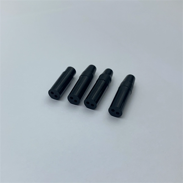
It is usually welded or threaded, and the two flanges are joined together by bolting them with gaskets to provide a seal, providing easy access to the piping system. A pigtail serves as a bridge between multiple conductors and a single terminal. These short wire segments solve space constraints in junction boxes by creating a central hub. Imagine three wires needing to. This is where the pigtail connector becomes an essential solution. A pigtail connector is a short length of wire with a factory-terminated connector on one end and bare, exposed wires on the other. It serves as a bridge, allowing technicians to repair specific connection points without disturbing. What is a Flange? Flanges are devices used to connect pipes, valves, pumps, fittings, and other equipment such as filters and pressure vessels. It ensures a secure connection by combining wires with a wire connector, like a twist-on connector or a wire nut, and then linking them to the intended terminal or fixture. Pigtails serve. Pigtail connections are most frequently used to ground a switch or electrical outlet and for electrical devices that need to connect to multiple circuit wires. They also come in handy to lengthen circuit wires that are too short to reach a device. It provides a plug-and-play repair solution that restores OEM fit, seal, and electrical reliability.
[PDF]
Can two switches with fiber ports be directly connected through fiber ports? The answer is yes. The connection between two or more Ethernet switches in a certain way (Uplink port, etc. ) is. Switch optical port intercommunication means that the optical fiber ports of two switches are connected to each other to achieve the purpose of network connection. Fiber optic technology is widely used in networking due to its high-speed data transmission capabilities and long-distance coverage. SFP transceiver modules almost always require two fiber optic cable strands. Fiber provides: Increased internet signal bandwidth. ) is called the cascade. Traditionally, network switches have been connected using copper cables, but with the increasing demand for high-speed and reliable connectivity, fiber optic cables have gained prominence. This article aims to provide a comprehensive understanding of how network switches are connected to fiber.
[PDF]

Can we connect the multimode with single mode fiber directly? In general, single-mode fiber and multimode fiber cannot be directly connected. That is because SMF and MMF have different core diameters and light propagation modes. Multi-mode may use SC, LC, or MPO connectors. It depends on your system setup. Signal Transmission: Single-mode fiber transmits light in a single path. This keeps signal loss and dispersion low for longer distances. This increases the risk of. It's possible because Multi-mode optical cables have a very wide fiber core – 62. 5µm (OM1) or 50 µm (OM2/OM3/OM4/OM5) – so this 1000Base-SX SFP's transmitting interface is conditioned to connect the LED source to this very wide fiber core. In contrast, the single-mode optical cable core is narrow –. Fiber optic communication is a method of transmitting information from one place to another by sending pulses of light through an optical fiber. The light forms an electromagnetic carrier wave that is modulated to carry information. The problem is how to realize SMF connects to the end equipment multimode modules. For the latter, the problem is. But what happens when you need to connect an existing multi-mode campus network to a new single-mode service provider link? You can't just splice them together. This is where fiber conversion comes in.
[PDF]

The fiber optic cable does not plug directly into a standard home router because the signal type must be translated. The fiber line terminates at the Optical Network Terminal (ONT), which is typically supplied and installed by the internet service provider. The ONT converts the light from th e fiber into electrical signals that run via an ethernet cable. The technician powers, tests, and activates the connection to confirm full speed and signal quality. * In some instances, the ONT. When it comes to land-based high-speed broadband connections, there are currently two competing technologies: Coaxial Cable vs. Fiber-optic, or Cable vs. This post will briefly explain the two and offer tips for handling their broadband terminal devices: the Cable modem vs. Additionally, you'll need a compatible. Fiber internet transmits data using light signals through fiber-optic cables, which differs from traditional DSL or cable internet. Most fiber ISPs. The process to connect fiber optic cable to router requires careful attention to detail, but I'll walk you through every critical step with the precision and clarity you deserve. This specialized equipment serves as the.
[PDF]
Choose an SFP module based on the fiber optic cabling that will be connected to the network switches. In addition, fiber cables can transmit data over several kilometers without signal degradation, making them ideal for connecting switches in large campus networks and between different buildings. As they do not emit electromagnetic signals, they're difficult to tap and secure against eavesdropping. Most modern SFP transceiver modules. Hi Experts, I have a basic knowledge of network and need some help. I need to connect 4 Floor Building with 4 Cisco 2960 - 48 ports switch each other and it needs to be through a fiber. So all PCs connected to each switch would reach the LAN/WAN from the other switch. (attached is the image here. Fiber optic cabling is increasingly used to connect network switches and other datacom equipment, especially in long-distance and mission-critical applications. Fiber provides: Increased internet signal bandwidth. Another way is to put a switch at Location B and interconnect using SFP modules. But is it possible to connect AB and BC cables using fiber optic patch cords ? Will it work in this fashion ? If this can work, I. We can use either the cat6 cable or fiber optical cable to link two network switch. One of the advantages of fiber optical cable is its fast speed. In this video, you will see how to link two network ports together to achieve 2G bandwidth between the switches. You even can connect more.
[PDF]

Fiber-optic cables are made by taking an individual fiber or bundle of fibers and adding coating and protective layers. A TOSLINK optical fiber cable with a clear jacket. These cables are used mainly for digital audio connections between devices. A fiber-optic cable, also known as an optical-fiber cable, is an assembly similar to an electrical cable but containing one or more optical fibers that are used to carry. A fiber optic cable consists of five basic components: the core, the cladding, the coating, the strengthening fibers, and the cable jacket. When searching for a fiber optic cable, we need to pay attention not only to the connectors, such as SC to ST fiber cable, LC to SC fiber patch cable, or SC to. Data transfer and telecommunications have been transformed by optical fiber technology. It consists of tiny glass or plastic fibers that can carry data as light pulses. The first low-loss optical fiber was created in 1970 by Robert Maurer, Donald. At its simplest, a fiber optic cable is a hair-thin strand of incredibly pure glass designed to transmit information using light pulses instead of electrical signals. This fundamental difference is why it's so fast and efficient. The process relies on a principle called Total Internal Reflection. The optical fiber transmits the signal, the strength member provides tensile and crush resistance, and the jacket protects the overall cable from the environment. Govind Agrawal, the Dr. Wyant Professor of Optics at the.
[PDF]

Yes, the Xiaomi Router BE5000 is fully compatible with virtually all standard fiber Optical Network Terminals (ONTs) and ISPs worldwide, regardless of region, provided the ONT outputs a standard Ethernet signal. Fibre-optic full gigabit router, delivering faster connection speeds Fibre-optic full gigabit for high-speed broadband over 100Mbps The Xiaomi Router AC1200 includes one gigabit WAN port and two gigabit LAN ports, easily achieving network speeds of 100Mbps and above. Compared with 100-megabit. Upgrading to a fiber optic router for the home, such as the Xiaomi BE5000, can unlock true fiber speeds by supporting 2. 5G ports, Wi-Fi 7, and efficient mesh networking, ensuring reliable coverage and performance across multiple devices and rooms. Compared with 100-megabit ports, it allows you to better utilise every megabit of bandwidth. Instead of a modem, fiber connections require an Optical Network Terminal (ONT), a device that converts fiber signals into an Ethernet connection. This means you don't need a specialized. Can I use SQM for 75 or 100 mbps without reducing the speed too much? The Mi Router has a CPU of 880 mHz. Will the 300 mHz in between affect it much? https://openwrt. org/inbox/toh/xiaomi/xiaomi_mi_router_4a_gigabit_edition try SQM on. Connect the power adapter to the router. Press and hold the button for 5 seconds to restore the router to its factory settings. 3 × 10/100/1000 Mbps WAN/LAN auto-sensing port.
[PDF]

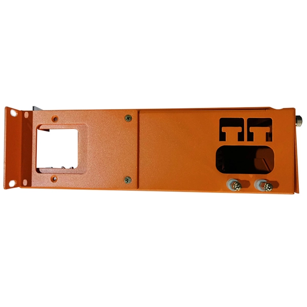
A distribution boxes acts as the load center and main distributor of electrical power within a building. Also called a distribution board, panel board, breaker panel, or electric panel, it is the central hub in an electrical system that divides incoming power into various subsidiary. 💡 Quick Answer: An outdoor electrical junction box is a weatherproof enclosure where electrical wires connect or split, required by code to protect connections from moisture, provide safe access for maintenance, and prevent electrical hazards in exterior applications. It takes the incoming power and safely distributes it to different circuits throughout your building. Whether in a home or an industrial facility, this box keeps your electrical setup organized, functional, and efficient. However, the key to. NEC Article 314 establishes requirements for the installation and use of electrical boxes, conduit bodies, fittings, and handhole enclosures. A conduit body is a removable-cover section of a conduit system that provides access at junctions or termination points. It receives power from the main electrical supply and divides it into separate circuits, each. An electrical sub panel, also known as a sub distribution board or sub circuit breaker panel, is a smaller secondary panel connected to the main electrical panel in a building.
[PDF]
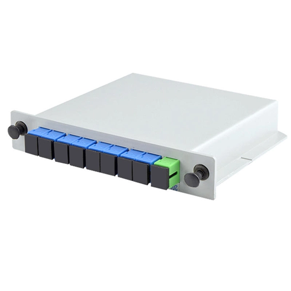
Its function is to split two incident light beams from two individual input fiber cables into sixty-four light beams and transmit them through sixty-four individual output fiber cables. A fiber-optic splitter, also known as a beam splitter, is based on a quartz substrate of an integrated waveguide optical power distribution device, similar to a coaxial cable transmission system. The optical network system uses an optical signal coupled to the branch distribution. These devices are commonly used in fiber optic networks to distribute signals to various endpoints. Optical splitters work by using a branching mechanism that allows the signal to be evenly. An optical splitter is a crucial passive fiber optic device that splits and combines optical signals. It can distribute the optical energy transmitted through a single fiber to two or more fibers in a predetermined ratio or combine the optical energy from multiple fibers into one fiber. Optical splitter.
[PDF]
148 (Grounding Conductor): Requires metallic junction boxes—and by extension, cabinet doors—to bond to ground using a designated grounding screw or clip. 28 (Box Materials): Metal boxes (like your cabinet) must be reliably grounded and bonded . NEC 250. A main bonding jumper is required to bond the service disconnect enclosure to the service neutral conductor [250. 28 (Box Materials): Metal boxes. All metal enclosures containing service conductors, such as meter socket enclosures and service disconnects, must be bonded to the grounding electrode system. 11 (D) is titled “Service Disconnecting Means” and requires a disconnecting means in compliance with Parts VI through VII of Article 230 to be provided to disconnect all ungrounded conductors of a power production source from the conductors of other systems. It is. Clearance: Electrical panels must be installed in a readily accessible area with a minimum clearance of 30 inches (762 mm) wide, 3 ft (36 inches or 914 mm) deep, and 6. 5 feet (≈ 2 meter) high in front of the panel. The panelboard's door (hinged cover) shall be able to be opened to a full 90°. Switchboards and panelboards are often called “the guts” of a premises wiring system. Article 408 covers the requirements for switchboards and panelboards that control power and lighting circuits (Fig.
[PDF]
Electric power distribution is the final stage in the. Electricity is carried from the to individual consumers. Distribution connect to the transmission system and lower the transmission voltage to medium voltage ranging between 2 and 33 kV with the use of. Primary distribution lines carry this medium voltage power to located.
[PDF]

The Dominican Republic is investing over $20 million to expand optical fiber in its southern provinces. This will bring high-speed internet to 145,000 residents across 23 municipalities and 46 districts. The project aims to provide free broadband to 343 public institutions. Get the Latest Releases & Updates About The Project The Dominica Geothermal Development Company Ltd (DGDC) informs the public that underground fibre optic cable installation works will be carried out from Friday, 13th March 2026, to Monday, 16th March 2026. The project route will extend from Trafalgar, along the Louisville/Copthall Road, onto the. The Caribbean Digital Transformation Project is a US$ 28 million project financed by the World Bank Group. These include 153. TendersOnTime, the best online tenders portal, provides latest Dominica Optical Fibre tenders, RFP, Bids and eprocurement notices from various states and counties in Dominica. TendersOnTime, the most comprehensive database for Government Tenders and International Tenders; collects information on. ROSEAU, Dominica, CMC – Dominica has signed an EC$200 million agreement with the Irish-based telecommunication company, Digicel, that is intended to meet the growing telecommunication and information communication and technology (ICT) needs of the island. Ends Cable and Wireless monopoly The.
[PDF]

A Saudi platform that aims to contribute to the automation of the procurement sector for companies and small and medium enterprises, and to reduce the gap between the seller and the buyer in Saudi Arabia to contribute to achieving the goals of Vision 2030 and developing local. A Saudi platform that aims to contribute to the automation of the procurement sector for companies and small and medium enterprises, and to reduce the gap between the seller and the buyer in Saudi Arabia to contribute to achieving the goals of Vision 2030 and developing local. KSA Business Gate is the Kingdom's premier informational portal and search engine. It provides real-time access to official and private tenders, projects, and business opportunities across Saudi Arabia and the Gulf region. Launched in 2020, it has grown into a trusted digital hub for accessing. The Cisco Catalyst 9300 Series switches are Ciscos lead stackable enterprise switching platform built for security, IoT, mobility, and cloud. They are the next generation of the industrys most widely deployed switching platform. Specifications Write a full review. Cisco Catalyst C9300-24S-E Switch. Procurement Excellence is the leading procurement platform for suppliers in Saudi Arabia for the private sector, revolutionizing procurement processes and fostering collaboration between buyers and suppliers. Don't waste time sending your inquiries by email. sa is an additional source for accessing procurement.
[PDF]