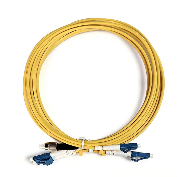
This article will compare waterproof connectors and non-waterproof connectors, highlighting their key differences, advantages, and best use cases in FTTH deployments. 🔍 What Are Waterproof Connectors?. In modern fiber optic deployments, one of the biggest challenges is ensuring stable and long-term connectivity in harsh outdoor environments. The comparison is typically triggered during outdoor deployments, edge network extensions, or hybrid indoor–outdoor transitions where connectors may be exposed. This is where Ruggedized Fiber Optic Connectors come in. Whether you are connecting a Remote Radio Unit (RRU) for Ericsson, Nokia, or Huawei, or setting up a harsh-environment sensing network, choosing the right waterproof interface is critical to preventing signal loss and network downtime. In. In today's fast-paced digital world, the choice of fiber optic connectors can significantly impact performance, reliability, and longevity of networking solutions. Among the varieties available on the market, waterproof fiber optic connectors have emerged as a superior option for many applications. In this blog, we will focus on comparing the performance of Mini LC.
[PDF]

This blog article entry considers the merits of choosing which of various low loss RF coaxial cables to use for IoT, LTE or LORA wireless applications where an external antenna is used to connect to router, gateway or terminal. The choice looks deceptively simple—pick a length, screw it on—but RF engineers know the truth: every extra meter quietly eats away at your link budget, especially once you cross 2 GHz. It's not just about length; the cable type, connector quality, and even mounting environment make a measurable. Audio generated by DropInBlog's Blog Voice AI™ may have slight pronunciation nuances. In this article, we will consider cables such as RG174, RG58, RF195. The cheap connectors have inferior dielectric between the poles as well as poorer grades of metal. The dielectric won't handle high power (KW range) as well and the center pin can more easily shift causing impedance problems if they are moved frequently. RF connectors are usually used with coaxial cables. They are designed to maintain the shielding that the coaxial design offers. The better and newer. Besides the wide range of RF connectors, Telegärtner also provides a considerable range of suitable coaxial low loss cables. Using this one-stop shopping option at Telegärtner makes your purchasing process even more efficient. The main use of low loss cables are all kinds of wireless applications.
[PDF]
This study presents the experimental investigations on heat transfer and airflow in a closed refrigerated display cabinet. Air and product temperatures and air velocity were measured with thermocouples and.
[PDF]

In part one of GIGABYTE Technology's latest Tech Guide, we explore the industry's most advanced cooling solutions so you can evaluate whether your data center can leverage them to get ready for the era of AI. 9 thermal guidelines applied to AI data center cooling — H1 high-density class, B200/GB200 implications, and what's coming in the next revision. Liquid. As Artificial Intelligence (AI) and High-Performance Computing (HPC) workloads drive rack densities beyond 50kW, traditional air cooling is reaching its physical and economic limits. Liquid cooling—specifically Direct-to-Chip (D2C) or Cold Plate technology—has emerged as the standard solution for. Modern AI accelerators have dramatically increasing power requirements, with TDPs rising from 300W (V100) to over 1,400W (MI355X) Heat Output = 700W × 0. 5W thermal BTU/hr = 696. Traditional air-cooling methods are struggling to keep pace with cooling the data center. Compute infrastructures for training large AI models are similar to high-performance computing (HPC) systems, which have long been used for demanding tasks in fields such as engineering, scientific research and finance. Industry insiders familiar with the natural progression of the modern data center will.
[PDF]
High-definition temperature sensing based on the natural Rayleigh backscatter in optical fiber delivers a virtually continuous line of temperature measurements with sub-millimeter spatial resolution. 1. Map temperat.
[PDF]
We describe a theoretical and experimental study of an intensity-based, dual-wavelength referenced fiber optic temperature sensor utilizing temperature-induced spectral shifts of optical thin-film interference coatings, deposited on a sensor fiber end. We present coating design considerations that. This study proposes the development of a dual-wavelength optical fiber sensor (DWOFS) that integrates two optical fiber structures in a multimode transmission line to measure the refractive index and temperature of a liquid concurrently. One structure is based on a refractive index sensor that. ter. The dual-wavelength fiber laser has a ring cavity composed of two FBGs with central wavelengths of 1550. Through monitoring the wavelength shift and the output power difference of the dual-wavelength fiber laser, the simultaneous measurement for RI and temperature is. To improve the sensitivity measurement of temperature sensors, a fiber optic temperature sensor structure based on the harmonic Vernier effect with two parallel fiber Sagnac interferometers (FSIs) is designed, and theoretical analysis and experimental testing are conducted. The FSI consisting of. Fiber-optic high-temperature sensors are gradually replacing traditional electronic sensors due to their small size, resistance to electromagnetic interference, remote detection, multiplexing, and distributed measurement advantages. This paper reviews the sensing principle, structural design, and.
[PDF]

Home and business fiber optics projects typically range from a few hundred to several thousand dollars, depending on run length, fiber type, and labor needs. The main cost drivers are materials, installation time, and environmental factors that affect trenching, conduit, and terminations. Commercial building installations with 100-200 network drops generally range from $15,000 to $30,000. Single-mode fiber costs less per foot than multimode fiber, but it requires more. What is Fiber optic network design? Fiber optic network design involves the planning, routing, and drafting of Fiber cable layouts to support high-speed data transmission. It includes detailed mapping of backbone, distribution, and drop connections for FTTH, FTTP, FTTx, and enterprise networks. Fiber optic network design refers to the specialized processes leading to a successful installation and operation of a fiber optic network. It includes first determining the type of communication system (s) which will be carried over the network, the geographic layout (premises, campus, outside. According to ResearchAndMarkets, the global market for fiber optics was estimated at $5. 8 billion in 2022 and is expected to reach $11. This is the dominant broadband access technology across half of OECD countries today. The price landscape varies from basic drop cables to enterprise backbone runs, with per foot and per reel pricing common in estimates. This guide presents cost ranges.
[PDF]

We propose an optical circulator formed of a magneto-optical cavity in a 2D photonic crystal. With spatially engineered magnetic domain structures, the cavity can be designed to support a pair of counterrotating states at different frequencies. By coupling the cavity to three waveguides, and by. ulator on silicon with 12dB isolation ratio. By locally switching the direction of the magnetic field on chip, we can dynamic es nators; (230 o integrate in photonic integrated circuits. They are widely used in WDM networks, opt cal amplifiers, and optical sensing systems. Previous demonstrations. A three-port circulator for optical communication systems comprising a photonic crystal slab made of a magneto-optical material in which an magnetizing element is not required to keep its magnetic domains aligned is suggested for the first time. Coupled mode theory is used to predict the broadband condition. It is shown that the rod–waveguide coupling. Abstract—In this paper, we propose a development of a T-shaped circulator based on a 2D-photonic crystal, which has a simple and compact structure. This structure makes the non-reciprocal transmission of electromagnetic waves. Through a series of adjustments in the crystalline geometry and using.
[PDF]

The purpose of the present invention is to provide an explosion-proof and flame-retardant distribution box, which has good explosion-proof and flame-retardant effect, strong impact resistance, is not easy to disperse, and has reliable safety performance. Flameproof enclosure (Ex d IIB+H2), which can be used as feed distribution equipment in control and distribution system (such as distribution box, switch box of main circuit, control box, terminal box or motor starting box etc. ) ·Enclosure: stainless steel. Equipped with specialized hinge. Substructure (use SSS=) and similarity (use ~) searches are limited to one per search at the top-level AND condition. Exact searches can be used multiple times throughout the search query. Searching by SMILES or InChi key requires no special syntax. To search by SMARTS, use SMARTS=. To search for. REV. Durable Hexlon Explosion Proof Distribution Boxes and Electrical Enclosures, IECEx and ATEX certified for Zone 1 and Zone 2. Design explosion-proof distribution box (control box) to meet equipment category and group requirements; b. They include fully modular low- and medium-voltage Ex-e, Ex-d, and Ex-p solution components, from Switchgear, Splitter Boxes, Junction Boxes, Ring Main Units, Power Supply, Motor.
[PDF]

Optical attenuators use several principles in order to accomplish the desired power reduction. The types of attenuators generally used are fixed, stepwise variable, and. An optical attenuator is a passive device that is used to reduce the power level of an optical signal. The attenuator circuit will allow a known source of power to be reduced by a predetermined factor, which is usually expressed as decibels. Key requirements include minimal effect on the beam profile, low wavelength and polarization dependence, and sufficient power handling capability. The basic types of optical attenuators are fixed, step-wise variable, and continuously variable. Since too much light may saturate the fiber optic receiver, optical attenuators are often deployed in the system to reduce the light power and achieve the best fiber. An attenuator is a device designed to reduce the intensity of electrical and electromagnetic oscillations smoothly, stepwise, or at a fixed rate. It primarily ensures the power or amplitude of a signal is lowered without significantly distorting its waveform. Attenuators are extensively used across.
[PDF]

Relay protection is the discipline of designing schemes that detect faults, coordinate relays, and isolate equipment without outages. It emphasizes selectivity, coordination, fault response, and system behavior rather than individual relay devices. Relay protection is often misunderstood as a. A protective relay is an intelligent electrical device designed to detect faults in power systems and initiate corrective actions such as tripping a circuit breaker. : 4 The first protective relays were electromagnetic. This document provides recommendations, background and philosophy on relay protection that is not available in M07. The facilities to which this Document applies are generally comprised of the fol-lowing: In analyzing the relaying practices to meet the broad objectives set forth, consideration must. What is a Protective Relay? A protective relay is an intelligent device that senses abnormal electrical conditions, such as overcurrent, under-voltage, or frequency deviations. It initiates the operation of circuit breakers to isolate the affected section. This prevents damage to equipment, reduces. Protective relays and devices have been developed over 100 years ago to provide “lastline”of defense for the electrical systems. They are intended to quickly identify a fault and isolate it so the balance of the system continue to run under normal conditions. The selection and applications of.
[PDF]

We are offering a comprehensive, fabrication-ready CAD file for a standard electrical distribution box. This isn't just a simple layout; it's a detailed mechanical drawing intended for electrical engineers, panel builders, and fabricators. High-performing, reliable product solutions that transmit data, power and signal in cars, planes, power grids, appliances, electro. Discover all CAD files of the "Power Distribution Boxes" category from Supplier-Certified Catalogs ✅ SOLIDWORKS, Inventor, Creo, CATIA, Solid Edge, autoCAD, Revit. The CAD files and renderings posted to this website are created, uploaded and managed by third-party community members. This content and associated text is in no way sponsored by or affiliated with any company, organization, or real-world good that it may purport to portray. It is running model of. Development of a distribution box for a meter. Download CAD block in DWG. 22 KB). Disassembly of a distribution box of a Perkins engine Already Subscribed? Free download Distribution box in DWG format or CAD block. This component, also known as a breaker panel or consumer unit, is the central nervous system for power management in any residential, commercial, or industrial setting. We design and manufacture a range of electrical products for the distribution, protection, control and management of electrical systems in low voltage environments. We help our customers to design and build their own.
[PDF]

This guide provides CISOs and IT leaders with an in-depth look at network security architectures. Perimeter security is the first line of defense, protecting the network from external threats. It includes firewalls, intrusion prevention systems (IPS), and other security devices that control network traffic at the network's boundary. When effectively designed, network security reduces threats like unauthorized access and malware from impacting your network or. Network security architecture is a strategy that provides formal processes to design robust and secure networks. Effective implementation improves data throughput, system reliability, and overall security for any organization. It explains the key concepts in plain language, dives into the core components, shares a framework for. Microsoft Defender for Cloud provides cloud security posture management (CSPM) and cloud workload protection (CWP). It assesses your resources for security compliance, provides a secure score to track your posture, and offers threat protection across Azure, on-premises, and multicloud workloads. It encompasses hardware, software, policies, and procedures.
[PDF]