This comprehensive checklist helps facility managers and maintenance personnel identify potential issues with fire-rated cable tray covers before they lead to compromised fire safety, electrical hazards, or building code violations. Regular inspection of fireproof cable tray covers is essential for maintaining electrical system safety and fire protection integrity. Why Are Cable Tray Inspections Important? Cable trays serve as the backbone of electrical systems, ensuring. The fire-resistant cable tray and conduit assemblies play a critical role in maintaining safe and compliant industrial operations, particularly within hazardous locations such as chemical plants, oil refineries, and manufacturing facilities. One of the most widely recognized testing standards for. Scope: Firestopping for busway, cable trays, cables, and trunking passing through walls in enclosed electrical installations. Where cables pass through shafts, walls, slabs, or enter electrical panels or cabinets, openings shall be tightly sealed with firestopping materials in accordance with. Fire safety is paramount in any electrical system, and cable trays play a crucial role in ensuring the protection and reliability of the infrastructure. At Hutaib Electrical, we understand the importance of implementing robust fire safety measures to safeguard both people and property.
[PDF]

Based on analysis on the dispersion of the optical system of a MEMS-based VOA, we provide a method to reduce the WDL significantly with minor revision on the end-face angle of the collimating lens. 📦 For purchasing, use the RP Photonics Buyer's Guide for variable optical attenuators. It provides an expert-curated supplier directory, buyer-focused technical background information, and structured selection criteria to support professional procurement decisions. Variable optical attenuators are. An optical attenuator, or fiber optic attenuator, is a device used to reduce the power level of an optical signal, either in free space or in an optical fiber. The basic types of optical attenuators are fixed, step-wise variable, and continuously variable. Optical attenuators are commonly used in. Applications in broadband optical fiber communication system need variable optical attenuators (VOAs) with low wavelength-dependent loss (WDL). What Are Fiber Optic Attenuators? Fiber optic attenuators, also called optical attenuators, are passive. Optical attenuators are categorized based on their attenuation mechanism and adjustability: Fixed Optical Attenuators: These attenuators reduce the signal power by a predetermined value and are used in applications where a constant level of attenuation is required. It works by dissipating a portion of the optical power passing through it, thereby lowering the overall power level. Fiber optic attenuators.
[PDF]

Therm-X is a specialist in thermal systems, temperature sensors, heaters, thermocouples, controllers and resistance temperature detectors (RTDs) for renewable technologies. We have designed and co-developed temperature sensitive process equipment for solar, fuel cells, and other. In this comprehensive guide, you'll discover how temperature monitoring systems optimize photovoltaic power plant performance. We. Our Temperature Sensors ensure reliable and accurate temperature readings in all conditions. Constructed with premium materials and calibrated for precision, these sensors are designed for durability and stability, providing dependable performance over time. This TI Design addresses the key need of a highly cost-optimized monitoring and communication subsystem for solar module level power electronics (MLPE). This design. In addition to the standard line, ACS is able to offer customized solutions thanks to its more than 60 years of experience in designing customized environmental simulation chambers, its technical know-how and the close attention given to the requests of all our customers. Example of a chamber. We have designed and built simple custom temperature control solutions from single zone 150W panels up to large +850kW multi-zone/multi-circuit panels with a full HMI and plant-wide DCS integration. Below are some custom features we can add to your panel. Contact us to discuss your specific.
[PDF]

This video provides a detailed walkthrough of designing and simulating an automatic light control system using Light-Dependent Resistor (LDR) and Triac in Proteus Software. Last updated on 13 August 2025 by Admin-Lavi Leave a Comment This article talks about Light Controlled Switch Circuit using IC LM311 and LDR. It simple and very useful and it feel light change near it. We find this circuit in many place like automatic light, street lamp and security system. Main. ABB's Control Room offering includes a comprehensive range of solutions designed to optimize the operator workspace for critical 24/7 processes across various industries. The project demonstrates how to create a smart lighting system that turns on/off automatically based. more This video. The Intro Screen changes as you play with it. It has a Play Area and a Control Area. A Construction Area creates a building space for components added from a Circuit Component Toolbox. Build and navigate your circuits there. If Voltmeters and Ammeters are out of the toolbox, you can take. Common sense schematics let you name a node "+5V" and know that the simulator will do the right thing automatically, keeping your schematics compact and elegant. This circuit activates or deactivates connected loads, such as LEDs or light bulbs, based on ambient light levels.
[PDF]

The ring main circuit is commonly used for powering lighting circuits and plug sockets in residential and commercial buildings. It provides a safe and reliable method of electrical distribution, ensuring a consistent supply of power to each outlet. WATERPROOF DISTRIBUTION BOX: The power socket distribution box is made of high-quality ABS plastic material, with a size of 9. The waterproof grade of the shell is IP65. It is equipped with 4 IP44 waterproof sockets., can. The distribution box (DB box) helps safely and efficiently distribute electrical power. Today, electrical systems are essential for homes and industries. But what exactly is a power distribution box, and why is it so essential in our daily lives? The DB panel board controls the flow of electricity. Also known as a distribution board or breaker panel, it acts as the control hub, distributing power to different circuits and protecting them from overloads and faults. Here, we'll delve into what an electrical distribution box is, how it. Portable distribution boxes are mainly composed of core components such as shells, circuit breakers, sockets, terminals, leakage protectors, fuses, etc. As a protective "armor", the shell is mostly made of high-strength engineering plastics or aluminum alloys. Understanding the ring main circuit diagram is essential for electricians and individuals involved in electrical installations and repairs. The ring main circuit consists of a loop of cable, which.
[PDF]

The circuit diagram of the protective relay is made up of current transformer primary windings, current transformer secondary windings, relay operating coils, circuit breakers, and the tripping circuit. The relays are in round glass cases. The rectangular devices are test connection blocks, used for testing and isolation of instrument transformer circuits. In electrical engineering, a protective relay is a relay device designed to trip a circuit breaker when a fault is detected. : 4 The first. The working of a protective relay is based on continuous monitoring of electrical quantities such as current, voltage, frequency, and power. A typical protective relay circuit is shown below: Protective Relay Circuit Diagram The first part of the circuit consists of the primary winding of a CT. A relay is a four-terminal electrical switch, used to control any electrical circuit with an independent low-power signal and also to control various electrical circuits with a single signal. The terminals of the relay mainly include; common, coil, NO (normally open) & NC (normally closed). It functions as a watchdog by constantly surveying multiple system components including voltage, current, frequency, and phase angle. During a fault condition, there is a change. Protective relays and devices have been developed over 100 years ago to provide “lastline”of defense for the electrical systems.
[PDF]

This guide shows you how to organize circuit breaker wiring properly. You will learn to build a safe, efficient, and professional electrical system today. Circuit breaker wiring configurations involve organizing main switches, busbars, and branch breakers within a distribution box. While some homeowners may attempt this, it's highly recommended to hire a qualified, licensed electrician for circuit breaker box wiring. This is a complex and potentially dangerous task that involves working with high voltage electricity. Mistakes can lead to serious injury, fire, or damage to. A breaker box, also known as a circuit breaker panel, is an essential component of any electrical system. It is responsible for distributing electricity throughout a building, ensuring that each circuit receives the proper amount of power. To understand how a breaker box works, it is helpful to. When installing or troubleshooting a power distribution system, understanding how to correctly connect the main electrical supply to the control panel is crucial. The first step involves running a dedicated cable from the incoming supply to the distribution panel, ensuring it is rated for the load. How to read these diagrams. This page contains wiring diagrams for a service panel breaker box and circuit breakers including: 15amp, 20amp, 30amp, and 50amp as well as a GFCI breaker and an isolated ground circuit. Messy distribution boxes are dangerous and very hard to fix.
[PDF]

When a circuit breaker keeps tripping, the cause usually falls into one of three categories: overloads, short circuits, or ground faults. The key is knowing what's driving each one so you can troubleshoot it correctly. This comprehensive guide, compiled by ELECO's technical support team based on decades of global field experience, provides a clear, actionable roadmap to identify and solve the five most common causes of frequent tripping, saving you time and ensuring compliance on any international project. The bottom line: A tripping breaker means your electrical system is doing exactly what it's supposed to do. Now we need to figure out why. Understanding which one you're dealing with helps you know if this is something you can handle or if you need. Circuit breakers serve as your home's electrical guardians – they automatically cut power when detecting dangerous conditions. Occasional tripping is normal protection behavior, but frequent tripping signals underlying issues needing attention. It's a typical issue. Below, you'll find reasons why this occurs and tips to avoid it moving forward. Get a handle on your circuit breaker problems! Circuit breakers are protection.
[PDF]

Provides technical requirements concerning the construction, testing, and performance of metal cable tray systems. It is the first joint effort of NEMA and CSA International to put in one place standards for metal trays per both NEMA and CSA methods. Addresses shipping. Cable trays play a vital role in supporting electrical cables and wires in commercial, industrial, and utility installations. For proper installation, design, and maintenance, adherence to international standards is essential. One of the most recognized frameworks globally is the IEC standard for. association representing the major electrical equipment manufac-turers in the U. The Cable Tray ng standards, performance standards, test standards and application in this document have been tested extens ompetent professional en completely installed, without damage either to conductors or. CABLE TRAYS THE GLOBAL SPECIALISTIN ELECTRICAL AND DIGITAL BUILDING INFRASTRUCTURES TECHNICAL GUIDE Not all cable trays are equivalent. The mechanical and electrical characteristics, tests, certifications, overall quality management, recommendations mentioned in this technical guide only apply to. Not all cable trays are equivalent. For those of you that have experience working with cable tray systems, you have probably noticed the high-level of influence NEMA has in guiding cable tray management projects.
[PDF]

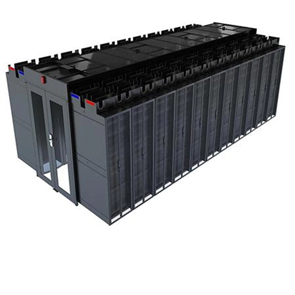
This guide provides essential best practices for server rack setup and organization, covering steps for effective installation, cable management, standards compliance, power distribution, cooling methods, and security measures. By following these practices, you can enhance your network's. An in wall network cabinet is a special type of enclosure that fits inside your wall. Unlike traditional floor-standing racks, these cabinets are recessed, which means they don't take up valuable floor space. They're designed to hold important networking equipment such as switches, patch panels. There are various options available, ranging from simple wall-mounted enclosures to larger floor-standing cabinets. Consider the amount of equipment you have and the future expansion needs when choosing the size of the cabinet. It should have enough space to accommodate your modem, router, network. Whether you're setting up a new office or streamlining an existing network, understanding the importance, types, and usage of network cabinets is crucial. In this comprehensive guide, we'll explore everything you need to know about network cabinets, transforming chaos into order in your network. Today, manufacturers are designing data equipment rated at 75W and 150W per square foot, and even higher because server vendors are introducing equipment as small as 1U in height-particularly with servers aimed at the Internet Service Provider (ISP) market.
[PDF]

This guide explains what a fiber optic termination box is, how it works in practice, where it is typically installed, and how to choose the right model for different network environments. What Is a Fiber Optic Termination Box?. A Fiber Termination Box, also known as a Fiber Distribution Box, is a crucial component in fiber optic networks. It serves as a termination point for optical fibers, providing a secure and organized space for connecting and managing fiber optic cables. It functions as a junction between the incoming fiber cable and the outgoing customer-side fiber cable, where one fiber can be spliced, patched. A fiber optic termination box is a core component in modern fiber optic networks, providing a secure and organized point for fiber termination, splicing, and distribution. It is widely deployed in FTTH, FTTB, and other access networks to ensure stable signal transmission from backbone cables to end. Fiber termination box (FTB), also known as optical terminal box (OTB), generally refers to a distribution box specially designed for fiber cable management (fiber patch cables/pigtails) in FTTH applications. To ensure consistent performance and longevity, it is essential to adhere to strict technical specifications.
[PDF]

This document provides specifications for various distribution boxes including dimensions, mounting sizes, and number of ways. It stipulates requirements for enclosure materials, installation dimensions, the mandatory "one equipment, one switch, one RCD" rule, mechanical structure, earthing systems. RB21 is a portable, safe, economic and easy to use pre-wired low voltage ready board with 2 (Two) sockets, 1 (One) lighting lamp and protection area. It has 4 (Four) mounting lugs suitable for wall installation and additional knockout for future use. It is suitable for residential (small holding. The World Bank is financing the National Electrification Analysis (NEA) on behalf of the GoA for which NRECA International (NRECA) was contracted in September 2019. The NEA project is designed to perform a geospatial evaluation of electrification access options to achieve GoA access goals by. This guide walks you through everything about electrical enclosure box sizes — from measurement standards and IP ratings to sizing formulas and common pitfalls. Before talking numbers, let's clarify what “size” really means. Dimensions included are length, width. IEC 62262 IK10.
[PDF]
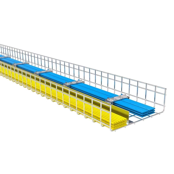
Standard splice plates can often provide a safe electrical path if they are UL Classified and bolted tight. However, you must use copper bonding jumpers if the tray is painted or has expansion joints for movement. A. The intent of this article is to review grounding practices for cable tray wiring systems. The Equipment Grounding Conductor is the electrical circuit's safety conductor. When designing a cable tray. Snap Track requires only single bonding jumper. Installation Guideline: Scroll to bottom of page to view All Bonding Jumpers Cut Sheets A bonding jumper is required to be installed with adjustable splices and expansion splices. If an EGC cable is installed in or on a cable tray, it should be bonded to each or alternate cable tray sections via grounding clamps (this is not required by the NEC® but it is a desirable practice). In addition to providing an. Do I have to use a bonding jumper at each cable tray splice point that is bolted tightly together? I currently have 3 runs of 24 tray about 80ft long. we have one expansion plate section per run in which I plan on using a bonding jumper at, I am curious about all other points You aren't even. Wire mesh cable trays are widely used in commercial offices, industrial facilities, data centers, and smart building infrastructure because they provide unmatched flexibility, excellent airflow, and fast, adaptable installation. Their open-grid design makes it easy to route, add, or modify cabling.
[PDF]