Comprehensive Guide to Civil Construction for Telecom Tower Sites In the ever-evolving landscape of telecommunications, the construction of tower sites serves as the backbone for reliable network connectivity. A communication tower foundation design is the structural blueprint that determines the anchor point of the tower on the ground. This article delves into the intricate process of civil construction tailored. Telecom (Telecommunications) towers are a generic description of radio masts and towers built primarily to hold telecommunications antennas. As such antennas often have a large area and must be precisely pointed out, such towers have to be designed and built to limit wind induced movement. So very. With excellent resistance to axial and lateral loads in both compression and tension, they're an efficient and durable foundation that's easy to remove and remediate. Monopole towers are popular in urban areas owing to their minimal footprint and adherence to city planning. The foundation type can be either mat foundation or monopile foundation. If you're planning a new installation, knowing the basics of these foundations can help you establish a secure and durable tower that will be a community asset for years to come.
[PDF]

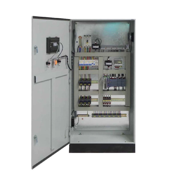
More specifically, these systems keep tabs on voltage, current, and temperature limits and control the disconnect relay. This allows them to disconnect themselves from the external application in case of malfunction. From a drop of rain to the shining sea, an energy storage system is like the earth's bodies of water (hear us out). In a battery energy storage system (BESS), the energy in the battery cells is like raindrops that combine to form a brook. Made of the combined energy from cells, these brooks combine. Battery energy storage systems (BESSs) investment is expected to grow to $103 billion by 2030. ) Battery systems aren't just designed to serve as local power backups, such as the systems used to power critical facilities (including hospitals and data centers) when the normal. When a 300 MWh battery energy storage system (BESS) in Arizona tripped offline during July's heatwave, operators discovered voltage fluctuations had overwhelmed its protection relays. Could your facility withstand such stress? As global BESS installations surge—projected to reach 1. Protection is necessary when energy and voltages combine from the modules, as well as from the battery racks. Fuses are an efficient. The electrical integration design of a Battery Energy Storage System (BESS) is based on the application scenario and includes various aspects such as DC, high/low voltage distribution, control power distribution, grounding, lightning protection, and safety standards.
[PDF]
The World Bank Group has approved plans to develop Botswana"s first utility-scale battery energy storage system (BESS) with 50MW output and 200MWh storage capacity. The World Bank will support the 4-hour duration BESS via a loan of US$88 million. Botswana has today marked a historic milestone in its energy transformation journey with the groundbreaking ceremony and signing of the Power Purchase Agreement (PPA) for the 500MW Maun Solar Photovoltaic (PV) Plant and 500MWh Battery Energy Storage System (BESS), one of the most ambitious. By 2030, 140MW of BESS will be needed to support the uptake of renewable energy generation. This financial boost will fund the construction of a 100-megawatt solar power plant and support a comprehensive renewable energy program designed to bring. Botswana has received an $88 million loan from the World Bank for its first utility-scale battery energy storage system (BESS). The 50 MW/200 MWh project will allow for the stable integration and management of renewable energy on the nation"s grid. In conclusion, the strategic imperatives. The World Bank has provided Botswana, one of the world's fastest-growing economies, with a loan to finance a 50 MW/200 MWh battery energy storage system, the nation's biggest such project to date.
[PDF]
Energy Internet integrates small-scale renewable energy systems, electric loads, storage devices, and electric vehicles for effective transaction of power backed by emerging technologies such as Internet of Things, vehicle-to-grid, and blockchain. Energy Internet, a futuristic evolution of electricity system, is conceptualized as an energy sharing network. Its features, such as plug-and-play mechanism, real-time bidirectional flow of energy, information, and money can lead to significant benefits and innovation in electricity production and. Future Electricity System Based on Energy Internet: Energy storage system.
[PDF]

Buyers typically pay a range for fiber optic cable per foot depending on fiber type, jacket, and shielding, plus installation considerations. This guide outlines typical cost ranges and the main drivers behind pricing to help formulate a budget and estimate expenses. The Fiber Broadband Association has partnered with Cartesian to research the cost of deploying fiber and provide insight on how these costs are evolving over time. In preparing this second edition of the Fiber Deployment Cost report, Cartesian gathered inputs from a wide variety of firms building. With 19+ years of experience installing fiber-optic cables at over 20,000 locations, we've seen how prices vary based on cable type, project scope, and installation complexity. This information can help project leaders engage with providers and network operators in their area. This data is based on cost information. As of August 2025, with global internet penetration reaching 67. 56 billion users worldwide, the demand for faster, more stable connections is at an all-time high. Fiber-optic technology, which transmits data via light through glass or plastic strands, offers unparalleled performance. Annual study tracks drivers to fiber broadband deployment cost WASHINGTON, D. — (January 22, 2024)—The Fiber Broadband Association today announced the results of its 2023 Fiber Deployment Cost Study, conducted by Cartesian, which provides the industry's benchmark to help fiber broadband service.
[PDF]
An optical line termination (OLT), also called an optical line terminal, is a device which serves as the service provider endpoint of a passive optical network. It provides two main functions: to perform conversion between the electrical signals used by the service provider's equipment and the fiber optic signals used by the passive optical network.to coordinate the multiplexing between the conversion. FeaturesOLTs include the following features: • A downstream frame processing means for receiving and churning an cell to generate a downstream frame, and converting a parallel dat. Most vendors integrate an entire fiber optic management system for ISPs to manage OLTs as well as client ONTs and as such are not interoperable. • • BT-PON.
[PDF]

Telescopic mast system with advanced vibration-dampening technology to minimize jitter and ensure stable communication and data transmission, even in the most demanding terrain and vehicle movements. Fireco designs and manufactures the most comprehensive line of standard and custom telescopic masts using high quality materials with industry leading engineering and quality testing practices to provide our customers with the world's best mobile masts. Will-Burt's telescopic masts and tower systems provide intelligent. Telescopic mast systems play a critical role in modern field operations—enabling elevation of cameras, antennas, lights, sensors, and communication gear in demanding environments. Whether for surveillance, broadcasting, defense, or emergency response, choosing the right mast system ensures reliable. Floatograph, along with its utility industry partner, Eversource Energy, developed the Rapid Pole® – Temporary Power Pole system to reduce customer downtime, allowing crews to re-energize a circuit in as little as 20 minutes. Floatograph's masts come in height options from 10 to 100 feet, and are. Advanced telescopic mast solutions designed for versatility in the field, providing crucial support for on-the-move (OTM) missions. Erecting the Telescoping Mast is made by simply connecting guys and brackets to the attached unique heavy duty rolled edge guy rings and clamps, extend the sections, insert the locking cotter pins, rotating the tubes to.
[PDF]
The Open Systems Interconnection (OSI) model is a developed by the (ISO) that "provides a common basis for the coordination of standards development for the purpose of systems interconnection." In the OSI reference model, the components of a communication system are disting.
[PDF]

Compared to conventional metallic cables, optical fiber provides an advantage of low loss (~ 0. 2dB/km) and wide bandwidth (several hundred MHz to THz) to enable long-distance, high-capacity communication. Fiber-optic communication is a form of optical communication for transmitting information from one place to another by sending pulses of infrared or visible light through an optical fiber. The light is a form of carrier wave that is modulated to carry information. Fiber is preferred. It was almost a century later before optical-based communication was put to practical use, thanks in large part to the invention of optical fiber and lasers. A laser's stable, highly directional beam of light (emitted from tiny semiconductor windows that measure just a few hundred thousandths of a. In 2020, we celebrated the 50th anniversary of the invention of low-loss optical fiber — an innovation that has transformed the way we connect and that lies at the cornerstone of our communications revolution. In a Corning lab on a Friday afternoon five decades ago, a single strand of glass and a. Fibre optics and optical communications is the use of thin strands of glass for sending information encoded into light over long distances. Total internal reflection prevents light inserted into one end of the fibre from escaping through the sides. Transferring information optically in this way.
[PDF]

The document discusses optical detectors used in fiber optic communications systems. It describes the functioning of PIN photodetectors and avalanche photodetectors (APDs). Their performance. An optital detector is a device that converts light signals into electrical signals, which can then be amplified and processed. Such detectors are one of the most important components of an optical fiber communcation system and dictate the performance of a fiber optic communication link. PIN Photodiode A PIN photodiode is a widely. Detectors perform the opposite function of light emitters. The most common detector is the semiconductor photodiode, which produces current in response to. It explains how these devices use optical fibers to measure quantities like temperature, mechanical strain, pressure, and vibrations by detecting changes in light propagating through the fiber. A central focus is on sensors based on fiber Bragg gratings, where the Bragg wavelength is sensitive to. Optical Power Meters: These devices measure the power of optical signals in fiber optic cables. This information helps in maintaining signal integrity and quality across the.
[PDF]

CT-S3T-2 tower section weight does not exceed 26 kg. Transmission tower weight per meter varies dramatically by voltage level: 35kV towers average 100-180 kg/m, 66kV systems run 150-250 kg/m, 110kV towers range 200-450 kg/m, 220kV structures reach 350-600 kg/m, and 500kV ultra-high voltage towers require 500-800 kg/m. This weight increases. Due to the complicated nature of tower infrastructure, it can prove invaluable to have an engineer approved recommendation for solutions that will accommodate your particular project. We offer a Tower Recommendation Proposal Consultation Service, providing a detailed report that you can use for the. 18m Telecom Tower Ma /www. inf. ASMTower automatically performs load calculation on telecom structures, wind load, ice load and dead load according to the following design standards: ASMTower performs wind and ice load calculations according to the chosen code and distributes the resulting loads, along with the weight of the. Get Latest Price from the seller Khan Enterprises - Offering Selp Sport Wi-Fi Tower, Size: 18 Mtr Rtt at ₹ 3500/meter in Bengaluru, Karnataka. Get WiFi Tower at lowest price | ID: 20500615430. Now, let's take a look at the pricing options: 1. Non-upgradeable: • 12 meters: R49,990. 00 ex VAT ex works PLUS R49,000. 00 ex VAT for site visit, civils, and installation.
[PDF]
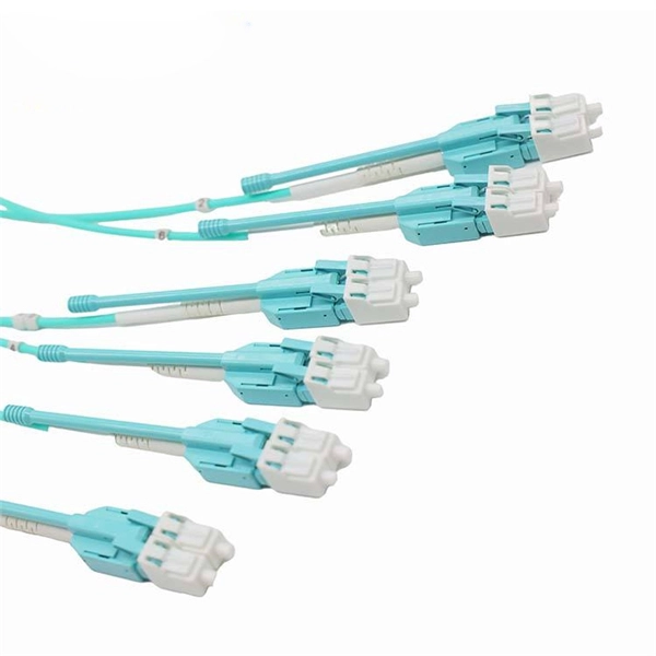
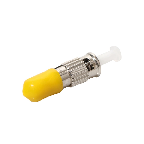
Engineered, manufactured, supported and delivered – with pride. We are a British based manufacturer of Copper Cabling Systems, Fibre Optic Products, Racks and Enclosures – deployed in Datacomms, Data Centres, FTTx & Telecom, Broadcasting and Smart Home Applications. British Cables Company is unique by any standards. Not only have we manufactured cables here in Blackley, Manchester since 1895, but also we are evolving into one of the most proficient service providers in the industry. British and proud? Absolutely! The business has always benefitted from. Alker Fibre Optics is an approved supplier direct to the UK MOD and a trusted partner for a number of specialist prime contractors within the military sector. We are always interested to work. Identify and compare relevant B2B manufacturers, suppliers and retailers Max. The company specializes in cabling and IT infrastructure services, highlighting its expertise in fiber optic cable supply and installation. With over 10 years of experience and a fully accredited team, they ensure. For 25 years Copper & Optic has been providing the highest quality electronic manufacturing services. We produce and supply cable and harness assemblies, PCB and fibre optic assemblies, potting and moulding, and automatic testing. Telecom ducting pipe is a non-flexible PVC pipe that carries telecom & data cables. Products are available for purchase online with free 30 day.
[PDF]

PDH (Plesiochronous Digital Hierarchy) is a telecommunications standard developed in the 1960s for transmitting large volumes of voice and data traffic over both copper and fiber-optic networks. The term "plesiochronous" refers to the fact that PDH operates with nearly synchronized timing between. This article briefly discusses the following stages of optical fiber communication: i) Plesiochronous Digital Hierarchy (PDH) ii) Synchronous Digital Hierarchy (SDH) iii) Wavelength Division Multiplexing (WDM) iv) Elastic Optical Networks (EONs) v) Space Division Multiplexing (SDM). Keywords:. This section of the SDH/SONET tutorial explains PDH concepts and the various PDH rates, including 2Mbps, 8Mbps, 34Mbps, and 140 Mbps. PDH (Plesiochronous Digital Hierarchy) traffic, such as DS-1, E1, DS-1C, DS-2, and DS-3, is encapsulated with extra framing bytes/octets. This encapsulation allows. This series of courses are based on the Navy Electricity and Electronics Training Series (NEETS) section on Fiber Optic cable systems. The NEETS material has been reformatted for readability and ease of use as a continuing education course.
[PDF]