
On the US market, a 5. 26 mm 2 (10 AWG) ground wire must be used, and in all other markets a 6 mm 2 must be used. Grounding of the units: Attach a ground wire from one of the threaded studs (A) at the bottom of the housing, to the mounting plate (B). Power from factory ground must be installed by a qualified electrician. Each DISTRIBUTION BOX and controller must be grounded. Whether you're a seasoned pro or just starting out, this comprehensive guide will give you practical. To define the technical specifications for the supply of Fibre Optic Overhead Ground Wire (OPGW) for installation on extra high voltage power lines, under the responsibility of Tasmanian Networks Pty Ltd (hereafter referred to as 'TasNetworks'). This standard applies to all OPGW purchased for. 4. FO-VC2 JOINT USE - VERICAL MIDSPAN CLEARANCES 48. FO-GB GROUNDING AND BONDING 49. FO-RI JOINT USE RISER. The requirement includes the design, supply, stringing and splicing of OPGW cable on 400KV, 220KV & 132KV Transmission Towers. This specification defines the design, material, performance and test requirements for fibre optic cable to support the fibre optic telecommunication needs. The work. IPMENT, STRUCTURES, ETC. IN ELECTRICAL STATIONS INCLUDING TRANSMISSION AND DISTRIBUTION SUBSTAT GR THAN 8 FT FROM THE FENCE. THE FENCE SHALL BE GROUNDED SEPARATELY FROM THE GRID UNLESS OTHERWISE NOTED ON THE A PROPRIATE PROJECT DRAWING. FOR FENC G O OUTSIDE CLEARANCE SPACING. SEE APPLICATION.
[PDF]

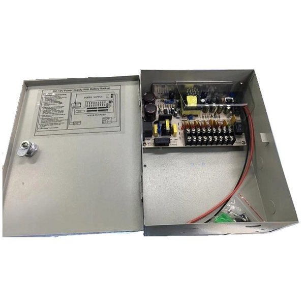
The proper installation of a distribution box involves placing it at the right height to ensure safety and convenience. 7 meters) high makes it easily accessible without the need to bend or stretch excessively. This height also safeguards the box from potential. An outdoor electrical distribution box serves as the critical junction point where incoming power lines are split into multiple branch circuits for outdoor installations, parking lots, building exteriors, and industrial facilities. Check for proper IP/NEMA ratings and material quality. Ensure safe placement: install in dry, accessible areas with good ventilation and at appropriate height (typically ~1. Practice good wiring: secure. Household distribution boxes can be installed on the ground or on the wall. Ground-mounted foundations should be 50 to 100 mm above ground level. When flused installed in the wall, the bottom is 1. 2m away from the ground. One outdoor receptacle is required at the front and rear of the house and in the perimeter of each deck, porch, patio, or balcony that is connected to the home. To run electrical. Clearance: Electrical panels must be installed in a readily accessible area with a minimum clearance of 30 inches (762 mm) wide, 3 ft (36 inches or 914 mm) deep, and 6. 5 feet (≈ 2 meter) high in front of the panel. The panelboard's door (hinged cover) shall be able to be opened to a full 90°.
[PDF]

A well-built fiber link rarely fails, but when it does the symptoms can be short, confusing, and expensive to chase. This guide lists the actual, field-proven problems technicians encounter most often and gives step-by-step troubleshooting actions you can copy into your maintenance routine. Keep. Fiber optic troubleshooting is an essential skill for network administrators, technicians, and engineers responsible for maintaining and repairing fiber optic systems. These high-speed, high-capacity communication networks are increasingly replacing copper cables, offering superior performance and. Ever wondered why your blazing-fast fiber optic internet suddenly slows to a crawl, or why your network connection drops out just when you need it most? You're not alone. Fiber optic cables are the backbone of modern industry and communication, but even the most advanced networks can run into. Fiber optic cables are the backbone of today's high-speed communication networks, powering everything from FTTH broadband to data centers. However, like any technology, fiber optic systems can encounter issues that affect performance. Understanding the common causes and solutions helps maintain. Even small forms of damage—from a bent cable to a rodent bite—can disrupt signals, cause costly outages, and require expensive repairs. This article outlines seven common issues that require professional fiber optic services.
[PDF]

This article outlines five specific steps for repair: 1) Identify the break; 2) Cut out the damaged section; 3) Strip the cable; 4) Trim the fiber ends; 5) Test the repair. DIY fiber optic cable repair kits are increasingly popular for those who prefer home repairs. This guide covers the essential tools and step-by-step procedures for low-loss fiber optic cable repair. Construction Activities: Accidental damage during construction. While a cut or damaged fiber optic cable can temporarily take your network down, it is possible to quickly fix the cable with the right tools. This wikiHow article will teach you how to splice a cut fiber optic cable back together with a fiber optic stripper and cutter and a fiber optic crimper. These cables consist of a core (glass or plastic) that carries light signals, surrounded by cladding to reflect light inward, a buffer for protection, and an outer jacket for durability. The actual steps may vary depending on the cable and/or connectors. Fiber optic cables are typically damaged in one of two ways: A premade fiber optic cable suffers connector damage when too. Don't let cable woes ruin your streaming binge or video conference; instead, explore these six proven ways to troubleshoot and fix your optical cable issues. Before diving into solutions, it's crucial to understand what an optical cable is and how it works. Begin by identifying the damage, which can be done using an Optical Time Domain.
[PDF]

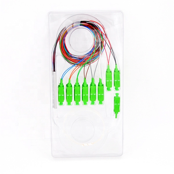
For a conventional optical module, we can easily judge the wavelength of the optical module from the color of the latch ring. For example, the black pull ring represents 850nm, and the blue pull ring represents 1310nm. Distinguish the wavelength by the color of the pull ring of the optical module In order to distinguish their own optical modules, different manufacturers can distinguish them by their wavelength, transmission distance, packaging, etc. In the complex infrastructure of data centers, optical modules are critical components that. The utility model discloses a pull ring device suitable for an optical module, and belongs to the technical field of optical communication. This article provides a professional guide on transceiver pull tab color codes by wavelength—spanning SFP, SFP+, CWDM, and BiDi modules—and introduces how LINK-PP standardizes. These modules convert electrical signals into optical signals, which transmit data over distances of fiber optic cables with minimal power loss. The topic of specifications and physical traits is one aspect of this question; another often-overlooked detail is the color of the pull tab. This modest. The ControlLogix® Architecture provides a wide range from high-speed digital to process control. The ControlLogix which allows input information and output status to Rockwell Automation recognizes that some of the terms that are currently used in our industry and in this publication are not in.
[PDF]

The main service panel is typically located in a home's basement or utility room. Some homes also have a subpanel—a smaller version of the main panel—to control electrical circuits in a garage, workshop, or other outbuilding. The National Electrical Code (NEC) does not specify a minimum height for an electrical panel, although practical access for service should always be considered. But there is a maximum height allowed for an electrical panel, which is based on the height of the highest breaker switch in the panel. NEC Article 408 covers switchboards, switchgear, and Panelboards installation and applications. Guidelines set by the National Electrical Code (NEC) provide a framework that ensures these installations adhere to stringent safety protocols. This article provides an exhaustive examination of the principles and standards governing the height at which electrical panels should be installed. The National Electric Code (NEC) includes the minimum standards for installing a circuit breaker panel box. These standards set the minimum safety standards for panel boxes. Tomorrow I'll be looking at a panel that was installed in a dining room knee wall 18" above floor. You can find electric panels inside cabinets, behind refrigerators, or inside clothes closets in older homes. Electrical panels.
[PDF]

First, connect each pre-terminated fiber optic cable to the adapter panel separately, making sure the ports correspond one-to-one; then fix the fiber optic adapter panel to the front panel of the distribution box with the bend radius control clip. In general, installing the optical fiber distribution box can be divided into three steps: installing the optical fiber distribution box on the rack, introducing the optical cable into the optical fiber distribution box, and planning the optical fiber path in the optical fiber distribution box. The. Bottom installation: Select a proper installation position in the equipment room and drill four holes in the floor according to the dimensions shown in the manual. Fix the rack to the ground with expansion bolts. Top installation: Dimensions of four connection holes on the top according to the. The Optical Distribution Box (ODB) is high-density 2-in-2-out fiber box solution. Designing with a compact size of 340x220x100mm, the cabinet accommodates 1x2,1x4,1x8 and 1x16 etc. The 4 ports are sized for main cable from 9 to 16mm in diameter, along with 16 3mm cables. Accessory Kits:. Install the optical fiber distribution box on the rack. Ensure that the box is installed firmly and horizontally, and the deviation of perpendicularity is not greater than 3mm.
[PDF]

The primary distribution box refers to the main distribution box, typically located in the distribution room. These boxes feature bottom entry and exit cables, front-opening doors, and main busbars connected with copper strips for optimal contact. The terms primary, secondary, and tertiary distribution boxes are relative. Let's make an example for clarity: A newly constructed residential area introduces a 10kV power line to a substation. From the transformer's low-voltage side (0. Main Distribution Board (MDB) 2. Unitized Panel. A distribution board (also known as panelboard, circuit breaker panel, breaker panel, circuit breaker, electric panel, fuse box or DB box) is a component of an electricity supply system that divides an electrical power feed into subsidiary circuits while providing a protective fuse or circuit. Two common types are the main panel and the distribution panel. They work together to keep your lights, appliances, and machines running safely. In this article, we'll explain what each panel does, how they are different, and when you need them. Whether it's for a home or a large building, knowing. At its core, a distribution box, also known as a distribution board, panelboard, or fuse box, is a protective enclosure that houses all the electrical components that control and protect the circuits in a building. It receives a single, high-amperage power feed and divides it into multiple.
[PDF]
This video shows real on-site footage of electrical installation, demonstrating safe and standardized wiring methods used by professionals. more Learn how to wire a distribution box step by step!. Plastic is lighter and good for indoor setups. Choose based on where you'll install the box. Inside the box, you'll find things like circuit breakers, busbars, terminal blocks, and wires. These parts control and distribute the electricity to different circuits safely. Some boxes also include DIN. Strictly speaking, the word “Distribution Box (D-box)” can refer to two categories: electrical distribution boxes and septic tank distribution boxes. This article mainly talks about the first one. I'll cover these four popular conduits: Remember, electrical conduits can be either rigid or flexible, and they come in various materials like metal, aluminum. NEC Article 314 establishes requirements for the installation and use of electrical boxes, conduit bodies, fittings, and handhole enclosures. A conduit body is a removable-cover section of a conduit system that provides access at junctions or termination points. Article 314 applies to: These. Where metal boxes or conduit bodies are installed with messenger-supported wiring, open wiring on insulators, or concealed knob-and-tube wiring, conductors shall enter through insulating bushings or, in dry locations, through flexible tubing extending from the last insulating support to not less.
[PDF]
Protect border security against illegal crossings, smuggling and unauthorized intrusions with a 24/7, real-time fiber optic perimeter intrusion detection system (PIDS) that can be mounted on fences, buried underground or deployed in a top-of-wall configuration. AP Sensing's Distributed Acoustic Sensing (DAS) technology delivers real-time perimeter and border protection by transforming standard optical fibers into dense acoustic sensor arrays. Acting as a Perimeter Intrusion Detection System (PIDS), DAS provides continuous, highly precise monitoring. It. The basic idea of fiber sensing technology is to utilize optical fibers as distributed optical sensors to detect and monitor changes in temperature and strain in a fiber or detect vibrations (sound/acoustics) in the environment around a fiber. It can also be used to protect data conduits and buried pipelines. Advanced adaptive signal processing along with certified SMS/VMS integration options ensure the. Perimeter Intrusion Detection Systems are systems used in an external environment to detect the presence of an intruder attempting to breach a perimeter. Modern security systems, driven by. Technica Fiber Tech's Fence Rakshak is a Fiber Optic based Perimeter Intrusion Detection System (PIDS) that can make organisations fully secure by identifying intruders and blocking such access. Our turnkey solutions can identify any unauthorized intrusions, evaluate the situation, and track.
[PDF]
Flex electrical cable, often referred to as flexible cable or flex, is a type of wire that is designed to withstand repetitive bending and movement without damage. Article 400 covers the general requirements and applications for flexible cords as contained in Table 400. A “flexible cord” is two or more insulated conductors enclosed in a flexible covering. Figure 01 The NEC does not. What is a flexible cable? Flexible cables are cables that have multiple conductors (Class 5 or Class 6 conductors) that form the conductor and are insulated and sheathed in a lightweight, flexible material (usually plastic or rubber). Why choose flexible cables for domestic use? It is suitable for. These include flat flexible cable (FFC), stranded wire, power cables, control cables, and flexible electrical conduit. Each type meets specific needs across industries like automotive, electronics, and medical devices. Here is a quick look at how leading cable types are used worldwide: You can. Power distribution cables present a unique challenge to electrical wire interconnect system engineers. Unlike rigid electrical wiring, which is designed for static installations within buildings, walls, or. In any electrical system—whether powering lights in homes, machinery in factories, or robots in operation—cables are the unsung heroes, safely and reliably transmitting electrical energy. As the backbone of power distribution systems, cables connect power sources (such as circuit breakers) to.
[PDF]

In this video, we'll walk you through the process of wiring a home distribution box with a detailed connection diagram. Whether you're an electrician or a DIY enthusiast, this guide will help you understand the basics of home electrical distribution. more Welcome to our channel! In this video. An electrical panel box, also known as a breaker box or a distribution board, is a crucial component of any electrical system. It serves as a central hub for distributing electricity throughout a building, ensuring that power is delivered safely and efficiently to all the required locations. What is Distribution Board? Distribution board. Hey, in this article we are going to see the Single Phase Distribution Box Wiring Diagram and Connection Procedure. And all the switching and protective devices are installed in the. Are you ready to master the skill of building electrical panels? This detailed guide provides an excellent base for beginners. Learn about the essential components of panels, such as the circuit breakers and fuses that safeguard against hazards. Then, delve into complex wiring configurations. Single Phase wiring installation is the most common wiring in residential buildings. In Single Phase supply (230V in UK, EU and 120V & 240V in the US & Canada), there are two (one is Line (aka Phase, Hot or Live) and the other one is Neutral) incoming cables from the utility poles to the kWh energy.
[PDF]

This guide provides a detailed, professional procedure for installing a Residual Current Circuit Breaker (RCCB)—a device essential for protecting people from the severe danger of electric shock. The steps outlined here are fundamental to ensuring the RCCB functions. It is an electrical protective device that protects electrical circuits and devices from some electrical faults such as leakage faults, electrical shock, current unbalance due to equipment failure, etc. It works on the principle of sensing residual current which is why it is called a residual. Distribution board is a safe system designed for house or building that included protective devices, isolator switches, circuit breaker and fuses to connect safely the cables and wires to the sub circuits and final sub circuits including their associated Live (Phase) Neutral and Earth conductors. Residual-current devices, commonly referred to as RCDs, are used in many practical applications. They can be found in fuse boxes, electrical switchgears or industrial machine control systems. Therefore. To wire an RCD fuse box correctly, start by reviewing the diagram to identify each circuit and its corresponding components. Understanding the layout helps prevent mistakes and ensures safe wiring. floor in a multi storey building. The Sub distribution board is connected and supplied from the Main Distribution Board through different wires and cables rated.
[PDF]