
Mount individual circuit breakers in the designated positions within the distribution box. Each breaker should match the current rating and type required for its specific circuit. Ensure proper connection to the busbars and secure mounting to prevent loosening over time. Correct wiring methods for circuit breakers within distribution boxes are fundamental to ensuring electrical safety and compliance with established codes. The distinction between 1P and 2P circuit breakers plays a pivotal role in determining the appropriate protection level for various circuits. This guide shows you how to organize circuit breaker wiring properly. You will learn to build a safe, efficient, and professional electrical system today. Circuit breaker wiring configurations involve organizing main switches, busbars. Circuit breakers, as important components in distribution boxes, can protect circuits from the effect of overload and short circuits. It serves as a central hub for distributing electricity throughout a building, ensuring that power is delivered safely and efficiently to all the required locations. We'll also look at whether it's good enough for your home, and what to do if your panel needs an upgrade. We want to help keep your home powered safely and. A breaker box, also known as a circuit breaker panel, is an essential component of any electrical system. To understand how a breaker box works, it is helpful to.
[PDF]

Practice good wiring: secure grounding, neat cable management, proper insulation, and correct wire gauge and breaker size. Include protection devices like breakers, fuses, and surge protectors—each circuit should have its own protection. Comply with standards: Follow NEC, IEC . An electrical panel box, also known as a breaker box or a distribution board, is a crucial component of any electrical system. It serves as a central hub for distributing electricity throughout a building, ensuring that power is delivered safely and efficiently to all the required locations. In this video, we'll walk you through the process of wiring a home distribution box with a detailed connection diagram. Whether you're an electrician or a DIY enthusiast, this guide will help you understand the basics of home electrical distribution. more Welcome to our channel! In this video. Choose the right box based on environment (indoor/outdoor), load capacity, and durability. Check for proper IP/NEMA ratings and material quality. Ensure safe placement: install in dry, accessible areas with good ventilation and at appropriate height (typically ~1. It involves connecting wires and components properly, to ensure safety and efficiency. Good wiring is vital to prevent electrical hazards and keep appliances, lights, and other electrical devices functioning well. It receives power from the main electrical supply and divides it into separate circuits, each.
[PDF]
High-definition temperature sensing based on the natural Rayleigh backscatter in optical fiber delivers a virtually continuous line of temperature measurements with sub-millimeter spatial resolution. 1. Map temperat.
[PDF]
A distribution box, or DB box, is a circuit breaker enclosure. It is a vital part and central hub of any electrical system. The hub distributes electrical power from a single input source to various circuits throughout a building. A distribution box, also known as a power distribution box or electrical distribution box, is used to distribute electrical power safely to multiple circuits. Distribution. A distribution boxes is an essential device that manages the safe and efficient flow of electrical power throughout different areas of a building or facility. Today, electrical systems are essential for homes and industries. It is widely employed in residential, commercial and industrial set-ups for circuit control and protection. By knowing their great.
[PDF]

In this guide, learn the basics of reading and interpreting electrical wiring diagrams. Follow Along on SkillCat: "Wiring Diagrams" Course! Want to test your knowledge? Skip to the quiz!. In this article, you'll learn how to read, understand and use a wiring diagram. An electrical wiring diagram could be a single page schematic of how a ceiling fan should be connected to the power source and its remote switches. A wiring diagram may include the wirings of a vehicle. For example, how. Electrical wiring diagrams are an essential tool for electricians, engineers, and automation technicians. Proper interpretation is crucial for understanding the operation of devices, diagnosing faults, and working safely with electrical installations. Understanding how to read electrical diagrams. In order to trace control system problems to the core, the ability to read and interpret various resources, from facility-level diagrams to machine-level wiring layouts, is critical. The engineering world is crammed full of drawings and diagrams of every possible kind. It shields sensitive equipment from dust, moisture, and. After reading and studying this handbook, electricians (or would-be electricians) will have a firm grasp on the many symbols used in electrical diagrams.
[PDF]

The ring main circuit is commonly used for powering lighting circuits and plug sockets in residential and commercial buildings. It provides a safe and reliable method of electrical distribution, ensuring a consistent supply of power to each outlet. WATERPROOF DISTRIBUTION BOX: The power socket distribution box is made of high-quality ABS plastic material, with a size of 9. The waterproof grade of the shell is IP65. It is equipped with 4 IP44 waterproof sockets., can. The distribution box (DB box) helps safely and efficiently distribute electrical power. Today, electrical systems are essential for homes and industries. But what exactly is a power distribution box, and why is it so essential in our daily lives? The DB panel board controls the flow of electricity. Also known as a distribution board or breaker panel, it acts as the control hub, distributing power to different circuits and protecting them from overloads and faults. Here, we'll delve into what an electrical distribution box is, how it. Portable distribution boxes are mainly composed of core components such as shells, circuit breakers, sockets, terminals, leakage protectors, fuses, etc. As a protective "armor", the shell is mostly made of high-strength engineering plastics or aluminum alloys. Understanding the ring main circuit diagram is essential for electricians and individuals involved in electrical installations and repairs. The ring main circuit consists of a loop of cable, which.
[PDF]

The circuit diagram of the protective relay is made up of current transformer primary windings, current transformer secondary windings, relay operating coils, circuit breakers, and the tripping circuit. The relays are in round glass cases. The rectangular devices are test connection blocks, used for testing and isolation of instrument transformer circuits. In electrical engineering, a protective relay is a relay device designed to trip a circuit breaker when a fault is detected. : 4 The first. The working of a protective relay is based on continuous monitoring of electrical quantities such as current, voltage, frequency, and power. A typical protective relay circuit is shown below: Protective Relay Circuit Diagram The first part of the circuit consists of the primary winding of a CT. A relay is a four-terminal electrical switch, used to control any electrical circuit with an independent low-power signal and also to control various electrical circuits with a single signal. The terminals of the relay mainly include; common, coil, NO (normally open) & NC (normally closed). It functions as a watchdog by constantly surveying multiple system components including voltage, current, frequency, and phase angle. During a fault condition, there is a change. Protective relays and devices have been developed over 100 years ago to provide “lastline”of defense for the electrical systems.
[PDF]

RCCBs (Residual Current Circuit Breakers) should be installed in key areas of your home's electrical system for maximum safety. The best place to install an RCCB is in the distribution board (DB box), which controls the electrical circuits throughout your home. This location ensures that the RCCB protects the entire electrical system by monitoring the current flow throughout. For added protection, you can also. A residual-current device (RCD), residual-current circuit breaker (RCCB) or ground fault circuit interrupter (GFCI) is an electrical safety device, more specifically a form of Earth-leakage circuit breaker, that interrupts an electrical circuit when the current passing through line and neutral. The primary function of an RCD is to monitor the electrical current flowing in a circuit and quickly disconnect the power supply if it detects an imbalance current (leakage of current to ground) between the live and neutral conductors. An RCD is essentially a current-operated ELCB and is commonly. RCCB Definition: A Residual Current Circuit Breaker (RCCB) is defined as a safety device that detects and interrupts a circuit when there is a leakage current to the ground. It can swiftly disconnect the circuit when a fault current happens and prevent wiring damage. In this article, we explain what an RCBO is and how it.
[PDF]

This guide shows you how to organize circuit breaker wiring properly. You will learn to build a safe, efficient, and professional electrical system today. Circuit breaker wiring configurations involve organizing main switches, busbars, and branch breakers within a distribution box. While some homeowners may attempt this, it's highly recommended to hire a qualified, licensed electrician for circuit breaker box wiring. This is a complex and potentially dangerous task that involves working with high voltage electricity. Mistakes can lead to serious injury, fire, or damage to. A breaker box, also known as a circuit breaker panel, is an essential component of any electrical system. It is responsible for distributing electricity throughout a building, ensuring that each circuit receives the proper amount of power. To understand how a breaker box works, it is helpful to. When installing or troubleshooting a power distribution system, understanding how to correctly connect the main electrical supply to the control panel is crucial. The first step involves running a dedicated cable from the incoming supply to the distribution panel, ensuring it is rated for the load. How to read these diagrams. This page contains wiring diagrams for a service panel breaker box and circuit breakers including: 15amp, 20amp, 30amp, and 50amp as well as a GFCI breaker and an isolated ground circuit. Messy distribution boxes are dangerous and very hard to fix.
[PDF]

A fiber patch panel is a mounted enclosure—either rack-mounted or wall-mounted—used to terminate, manage, and interconnect multiple fiber optic cables. It acts as a hub for organizing splices and patch cords, streamlining fiber management and preserving signal integrity. Propel Series Sliding Fiber Optic Panels for holding Propel modules, adapter packs and splice cassettes EPX Fiber Optic Panel available in either G2 or LGX/PNL 1U, 2U or 4U fixed or sliding configurations FMT (Fiber Management Tray) Series Fiber Optic Panels FOMS-FPS and FOMS-FPS-HD Fiber. Consolidate your fiber optic connections in industrial environments with our DIN rail patch panel, with a modular design and tool-free installation save space and simplify deployment. Consolidate your fiber optic connections in industrial environments with our DIN rail patch panel, with a modular. Belden offers several Fiber Patching Systems. Cable Organization:. FS offers FHD® FAPs and FHU™ 1U fiber patch panel with LC, SC, MTP®/MPO connectors in singlemode/multimode fiber to deploy medium for high-density fiber optic network applications. Foss FP-series front patch panels are made with the highest accuracy for precise fitting. All panels are tested according to both our own quality measures and international standards before they are sent to customers. In an FTTH network hub—whether a central office, local exchange, or data.
[PDF]

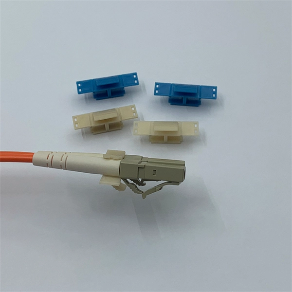
In this video, Joe would display how to connect SC fiber optical connector in 2 minutes. Related product:. Step 4 i s to affix the fiber to the connector. The fiber should be inserted into the connector until it is flush with the ferrule end. Step 5: Let the epoxy cure. These connectors ensure high-quality signal transmission, which is essential for reliable internet and communication services. SC APC connectors offer superior optical. There are many types of fiber optic connectors, including SC, LC, FC, ST, D4, MU, MT/MPO, etc. These connectors can be divided into single-mode and multi-mode fiber optic connectors according to their structure and purpose. To learn more about the types of fiber optic connectors, click here: Types. The global SC fiber optic connector market is valued at approximately 903 million USD in 2025 and is projected to grow steadily, which reflects its continuing role as a standard interface in fiber infrastructure, including plant backbones and industrial automation links, according to SC connector. SC fiber connectors, or Subscriber Connectors, are widely used in telecom and networking for their strong performance and easy handling. They're known for a secure push-pull connection that's quick to insert and remove.
[PDF]
The applicable subheading for the fiber optic panel/chassis and fiber optic patch tray, will be 9403. 8040, Harmonized Tariff Schedule of the United States (HTSUS), which provides for “Other furniture and parts thereof: Parts: Other: Other; Of metal. ” The rate of duty will be free. Item 1, part number LCXE-M1RU-BLK, is described as a fiber optic chassis with the capabilities of holding twelve fiber optic cables. The panel is produced from cold rolled. The merchandise is fiber optic patch panels that provide a consolidated point of demarcation for optical terminations, connections and cross connections within a passive, fiber optic network. They are designed to be mounted onto a wall or rack. All fiber optic patch panels will consist of the. Find verified buyers and sellers of Fiber Optic Patch Panel in 180+ countries along with their valid phone numbers and email ids. The top 3 Buyer countries for HS Code 851770 are “ PHILIPPINES ”, “ INDIA ”, “ PAKISTAN ”,. com if you have any questions or special project needs. The panel is produced from cold rolled. In the United States, customs duties imposed on imports from Asian countries have increased costs for Internet service providers and telecommunications companies, in many cases delaying infrastructure expansion and maintenance projects. In Latin America, several countries have adopted tariff.
[PDF]
Photovoltaic modules, or solar modules, are devices that gather energy from the sun and convert it into electrical power through the use of semiconductor-based cells. A photovoltaic module contains numerous photovoltaic cells that operate in tandem to produce electricity. A single PV device is known as a cell. An individual PV cell is usually small, typically producing about 1 or 2 watts of power. These cells are made of different. Photovoltaics (PV) is the conversion of light into electricity using semiconducting materials that exhibit the photovoltaic effect, a phenomenon studied in physics, photochemistry, and electrochemistry. Here is a description of their main features and of Enel Green Power's innovative solution. A semiconductor.
[PDF]


