
The term laser diode refers to a semiconductor device that emits laser light when an electrical current passes through it. Unlike regular LEDs that emit incoherent light, laser diodes produce coherent light—meaning the light waves are all aligned in phase and travel in a narrow . A laser diode (LD, also injection laser diode or ILD or semiconductor laser or diode laser) is a semiconductor device similar to a light-emitting diode in which a diode pumped directly with electrical current can create lasing conditions at the diode's junction. These devices are currently used in the fields of telecommunications and medicine and in industrial cutting and welding applications. This article discusses the characteristics common to laser. Laser diodes produce coherent light by stimulating photon emission at a semiconductor junction. Operational Mechanism: Laser diodes create light through stimulated emission within an optical cavity, with the light's properties influenced by the semiconductor. There are several variations of construction used for laser diodes, each aimed at achieving the maximum efficiency for converting electric current into laser light. 2 shows a simplified construction for a laser diode, which in this case is similar to a light emitting diode (LED) in that it.
[PDF]
Interferometric fiber optic current sensors (FOCS) employ circularly polarized light traversing a closed loop path around an electrical conductor's current-generated magnetic flux, which reflects off a mirror. The light experiences a reciprocal phase shift as the refractive index, and effective path length, is modulated by the presence of a magnetic field, which optically induces circular. OverviewA current sensor (FOCS) is a device designed to measure. Utilizing a single-ended optical fiber wrapped around the current conductor, FOCS exploits the (. As FOCS are resistant to effects from magnetic or electrical field interferences, they are ideal for the measurement of electrical currents and high voltages in or other environme.
[PDF]

Optical attenuators use several principles in order to accomplish the desired power reduction. The types of attenuators generally used are fixed, stepwise variable, and. An optical attenuator is a passive device that is used to reduce the power level of an optical signal. The attenuator circuit will allow a known source of power to be reduced by a predetermined factor, which is usually expressed as decibels. Key requirements include minimal effect on the beam profile, low wavelength and polarization dependence, and sufficient power handling capability. The basic types of optical attenuators are fixed, step-wise variable, and continuously variable. Since too much light may saturate the fiber optic receiver, optical attenuators are often deployed in the system to reduce the light power and achieve the best fiber. An attenuator is a device designed to reduce the intensity of electrical and electromagnetic oscillations smoothly, stepwise, or at a fixed rate. It primarily ensures the power or amplitude of a signal is lowered without significantly distorting its waveform. Attenuators are extensively used across.
[PDF]

We are offering a comprehensive, fabrication-ready CAD file for a standard electrical distribution box. This isn't just a simple layout; it's a detailed mechanical drawing intended for electrical engineers, panel builders, and fabricators. High-performing, reliable product solutions that transmit data, power and signal in cars, planes, power grids, appliances, electro. Discover all CAD files of the "Power Distribution Boxes" category from Supplier-Certified Catalogs ✅ SOLIDWORKS, Inventor, Creo, CATIA, Solid Edge, autoCAD, Revit. The CAD files and renderings posted to this website are created, uploaded and managed by third-party community members. This content and associated text is in no way sponsored by or affiliated with any company, organization, or real-world good that it may purport to portray. It is running model of. Development of a distribution box for a meter. Download CAD block in DWG. 22 KB). Disassembly of a distribution box of a Perkins engine Already Subscribed? Free download Distribution box in DWG format or CAD block. This component, also known as a breaker panel or consumer unit, is the central nervous system for power management in any residential, commercial, or industrial setting. We design and manufacture a range of electrical products for the distribution, protection, control and management of electrical systems in low voltage environments. We help our customers to design and build their own.
[PDF]

This guide provides CISOs and IT leaders with an in-depth look at network security architectures. Perimeter security is the first line of defense, protecting the network from external threats. It includes firewalls, intrusion prevention systems (IPS), and other security devices that control network traffic at the network's boundary. When effectively designed, network security reduces threats like unauthorized access and malware from impacting your network or. Network security architecture is a strategy that provides formal processes to design robust and secure networks. Effective implementation improves data throughput, system reliability, and overall security for any organization. It explains the key concepts in plain language, dives into the core components, shares a framework for. Microsoft Defender for Cloud provides cloud security posture management (CSPM) and cloud workload protection (CWP). It assesses your resources for security compliance, provides a secure score to track your posture, and offers threat protection across Azure, on-premises, and multicloud workloads. It encompasses hardware, software, policies, and procedures.
[PDF]

Home and business fiber optics projects typically range from a few hundred to several thousand dollars, depending on run length, fiber type, and labor needs. The main cost drivers are materials, installation time, and environmental factors that affect trenching, conduit, and terminations. Commercial building installations with 100-200 network drops generally range from $15,000 to $30,000. Single-mode fiber costs less per foot than multimode fiber, but it requires more. What is Fiber optic network design? Fiber optic network design involves the planning, routing, and drafting of Fiber cable layouts to support high-speed data transmission. It includes detailed mapping of backbone, distribution, and drop connections for FTTH, FTTP, FTTx, and enterprise networks. Fiber optic network design refers to the specialized processes leading to a successful installation and operation of a fiber optic network. It includes first determining the type of communication system (s) which will be carried over the network, the geographic layout (premises, campus, outside. According to ResearchAndMarkets, the global market for fiber optics was estimated at $5. 8 billion in 2022 and is expected to reach $11. This is the dominant broadband access technology across half of OECD countries today. The price landscape varies from basic drop cables to enterprise backbone runs, with per foot and per reel pricing common in estimates. This guide presents cost ranges.
[PDF]

We propose an optical circulator formed of a magneto-optical cavity in a 2D photonic crystal. With spatially engineered magnetic domain structures, the cavity can be designed to support a pair of counterrotating states at different frequencies. By coupling the cavity to three waveguides, and by. ulator on silicon with 12dB isolation ratio. By locally switching the direction of the magnetic field on chip, we can dynamic es nators; (230 o integrate in photonic integrated circuits. They are widely used in WDM networks, opt cal amplifiers, and optical sensing systems. Previous demonstrations. A three-port circulator for optical communication systems comprising a photonic crystal slab made of a magneto-optical material in which an magnetizing element is not required to keep its magnetic domains aligned is suggested for the first time. Coupled mode theory is used to predict the broadband condition. It is shown that the rod–waveguide coupling. Abstract—In this paper, we propose a development of a T-shaped circulator based on a 2D-photonic crystal, which has a simple and compact structure. This structure makes the non-reciprocal transmission of electromagnetic waves. Through a series of adjustments in the crystalline geometry and using.
[PDF]

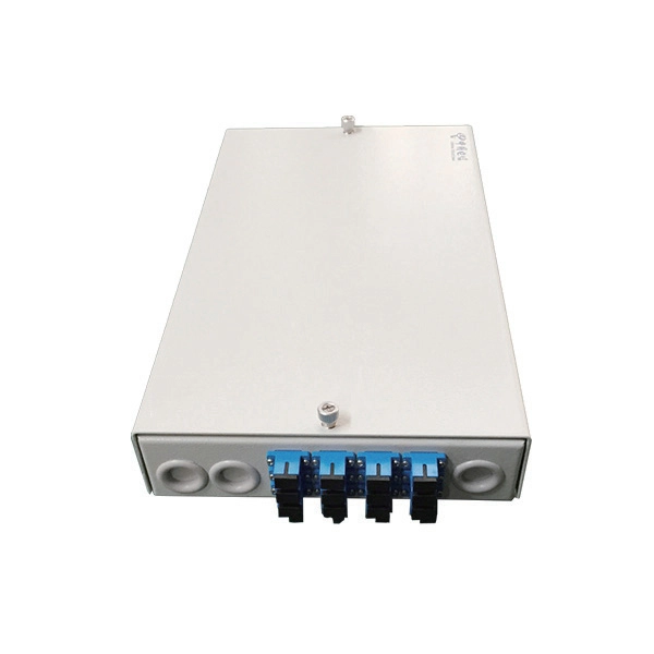
This complete guide explores everything you need to know about ODFs — from their structure, types, and key components, to installation best practices and modern design trends. Whether you're building a central office, data center, or FTTx distribution network, understanding the right ODF. An Optical Distribution Frame (ODF) is the central hub for fiber splicing, termination, patching, and cable protection in modern optical networks. This guide demystifies ODF, exploring their design, core functions, types, and how they. Fiber distribution hardware manages each fiber and connection point that is associated with active electronics. Why do operators, designers, and installers use additional fiber optic hardware racks for cable and fiber management? The active electronics are the most expensive part of the. A bad ODF can cause signal loss, slow repairs, and network outages. Let's talk about ODFs the way engineers and buyers need — with facts, clear advice, and practical steps. It's where. An ODF is a central hub in fiber optic networks, crucial for managing and organizing the variety of fiber-optic cables and connections entering a facility such as a telco central office (CO). Key points An optical distribution frame (ODF) is a central hub in fiber optic networks, crucial for.
[PDF]
In this paper, we present this new method of building OMS-OOCCN or its model. System design Our method applies three key information processing techniques such as geographic information system (GIS), simulation and expert system (ES) ones. We developed a specialized Geographic Information System for an internet service provider operating a fiber-optic network across multiple neighboring locations. Really, they are also the most important techniques for. Location Data (C. Summary of descriptive data (C. Manage Fiber Optics Network (maintenance &operation) (C. Final. A leading telecom infrastructure provider responsible for planning, deploying, and maintaining optical fibre cable (OFC) networks to expand digital connectivity across urban and rural regions. The client needed a reliable and accurate system to document, monitor, and manage thousands of kilometers.
[PDF]

Since there are two sections, separated by a circuit breaker, the fault on one section does not interrupt the other section of the bus. Maintenance of the bus section can be done individually, without affecting other. Variants include a sectionalized single bus, where one or more bus couplers divide the bus into segments to limit the extent of outages. Layout: one energized bus; each feeder/generator/transformer bay has a breaker and isolators. Sectionalization adds a bus coupler breaker and isolators to split. The relevant standard for High Voltage Switchboards is 62271-200. This standard covers High Voltage Switchboards with voltage levels above 1kV and up to 52kV. It is also used in small outdoor stations having relatively few outgoing or incoming feeders and lines. shows the single bus-bar system for a typical power station. The generators, outgoing lines and. Bus-bars are copper rods or thin walled tubes and operate at constant voltage. We shall discuss some important Bus Bar Arrangement in Power Station and sub-stations. All the diagrams refer to 3-phase arrangement but are shown in single-phase for simplicity. Single Bus-bar System: The single. This is a single bus system, with additional circuit breaker and isolators, making two different sections of bus, hence called a single bus system with bus sectionalizer. A busbar is a metal bar, usually made of copper or aluminum, that carries electricity inside switchgear.
[PDF]

The PE/PEN combination, comprising busbars, combination angles and baying brackets, supports type-tested configurations to IEC 61 439-1. For assembling 1-pole neutral or PEN conductors. Self-holding nut with knurled ring. Discover the robust selection of secondary pedestals at Hubbell, designed to enhance and secure your power distribution needs. These secondary pedestals are built to withstand harsh environments, ensuring long-lasting reliability and performance. Ideal for a variety of utility applications, they. These bars are tin-plated copper and have stainless steel terminals. Also known as bus bars, they serve as connection points between wires with ring or spade terminals. The underside is sealed, so the bars can be safely mounted to conductive surfaces. Distribution Bar Covers— Distribution bar. Busbars (bus bars) are integral to power distribution and serve numerous industries including automotive, industrial, and aerospace. Busbars are metal bars that can be composed of numerous alloys but are most commonly copper or aluminum. Typical busbar applications include switchgear, panel boards. For attaching the PE/PEN busbar 30 x 5, 30 x 10, 40 x 10 and 80 x 10 mm. With SIRIUS, SENTRON, SIVACON and ALPHA, we offer an innovative portfolio for standard-compliant and demand-oriented applications. Power Busbar System is a modular energy transmission and distribution system created by insulating current carrier Aluminium or Copper busbar conductors placed in a closed body.
[PDF]
This article delves into the intricate steps of busbar selection, preparation, and installation, ensuring efficient and safe power distribution. You'll discover the essential tools and techniques. FlexLine® busbars PSX go hand in hand with the flex terminals of the FlexLine® protection devices by following an one-size-fits-all approach. Whenever the neutral conductor terminals are not required, the flex terminals accommodate this busbar pin without any mechanical or electrical connection. BEIENE Smart 3 in 1 Busbar Processing machine is with our Intelligent 3D Busbar Program software Smartnest. From 3D Drawings, your busbar can be processed directly. Also can be optimized the production by the nesting function !. more BEIENE Smart 3 in 1 Busbar Processing machine is with our. 40 mm bar centre distance, 3-pole, space-saving plug-and-lock connection from the front, support suitable for top-mounting, all-round contact hazard protection. Our Mother company was founded in 1955 which is the Top Hydraulic research and developing institute in China! “Say Goodbye to CNC Machine, Open your Intelligent Times” this is our commitment to each customer !.
[PDF]
RCDs are designed to disconnect the conducting wires ("trip") quickly enough to potentially prevent serious injury to humans, and to prevent damage to electrical devices. A two-pole, or double-pole, residual-current device. The test button and connect/disconnect switch are colored blue.OverviewA residual-current device (RCD), residual-current circuit breaker (RCCB) or ground fault circuit interrupter (GFCI) is an. RCDs are designed to disconnect the circuit if there is a leakage current. In their first implementation in the 1950s, power companies used them to prevent electricity theft where consumers grounded returning circuits rath. with incorporated RCD are sometimes installed on appliances that might be considered to pose a particular safety hazard, for example long extension leads, which might be used outdoors, or garden equ.
[PDF]


