View inventory, pricing and order now for same day shipping!. View inventory, pricing and order now for same day shipping!. The beam splitter is an essential optical component that allows an incident light beam to be split into two or more partial beams. By using high-quality dielectric coatings on optical substrates, the beam splitter offers precise control over the ratio of reflected to transmitted light. This makes. Beam splitters are critical for managing optical power flow in a wide range of setups. Selecting the right component involves navigating trade-offs between power handling, polarization sensitivity, chromatic dispersion, and mechanical stability. A beam splitter is an optical device that separates. When working with lasers, it is often necessary to split a laser beam into two or more defined partial beams. There are a variety of beam splitters for these applications, with different advantages and disadvantages. Narrow down on the list of companies based on their location and capabilities. Bernhard Halle Nachfl. ZYGO specializes in providing large format, complex beamsplitters for use in aerospace.
[PDF]

How to Install a Fibre Connector into a Patch Panel (Easy fibre optic connector installation) How to Install a Fibre Connector into a Fibre Optic Patch Panel. How do you install fibre optic connectors?. Connecting a fiber patch panel to a switch is a critical step in setting up a fiber optic network. There are different types of connectors. In today's high-performance networks, fiber optic patch cables are the lifelines that ensure smooth data flow across switches, servers, and routers. Even the most advanced optical transceivers can only perform at their peak when paired with properly installed, clean, and precisely managed fiber. Choose an SFP module based on the fiber optic cabling that will be connected to the network switches. SFP transceiver modules almost always require two fiber optic cable strands. A Fiber Patch cord connects two devices. You plug it into a switch, router, or patch panel. It's ready to use out of the box. A pigtail is for splicing. You fuse it to a. With a railroad switch (patch panel), the train (data) can travel from A to B, C and even more destinations, otherwise it can only go from A to B, or C to D. This article, What Is a Patch Panel Used for?, has explained it thoroughly.
[PDF]
Choose an SFP module based on the fiber optic cabling that will be connected to the network switches. In addition, fiber cables can transmit data over several kilometers without signal degradation, making them ideal for connecting switches in large campus networks and between different buildings. As they do not emit electromagnetic signals, they're difficult to tap and secure against eavesdropping. Most modern SFP transceiver modules. Hi Experts, I have a basic knowledge of network and need some help. I need to connect 4 Floor Building with 4 Cisco 2960 - 48 ports switch each other and it needs to be through a fiber. So all PCs connected to each switch would reach the LAN/WAN from the other switch. (attached is the image here. Fiber optic cabling is increasingly used to connect network switches and other datacom equipment, especially in long-distance and mission-critical applications. Fiber provides: Increased internet signal bandwidth. Another way is to put a switch at Location B and interconnect using SFP modules. But is it possible to connect AB and BC cables using fiber optic patch cords ? Will it work in this fashion ? If this can work, I. We can use either the cat6 cable or fiber optical cable to link two network switch. One of the advantages of fiber optical cable is its fast speed. In this video, you will see how to link two network ports together to achieve 2G bandwidth between the switches. You even can connect more.
[PDF]

No, a 10G SFP (Small Form-factor Pluggable) module is designed to operate at 10 Gigabits per second (Gbps) and is not compatible with a 1 Gigabit per second (Gb) port. Therefore, a 10G SFP module will not work. When SFP optical module is inserted into the SFP port of Gigabit switch with fiber optic patch cable or copper cable, it can realize different distance transmission. For example, the maximum transmission distance is 160 km when using SFP1G-ZXC-55 optical module and LC duplex fiber patch cable, and. 10 Gigabit Ethernet (10GE, 10GbE, or 10 GigE) is a group of computer networking technologies for transmitting Ethernet frames at a rate of 10 gigabits per second. It was first defined by the IEEE 802. For example, when using the AE-SFP-ZX160 optical module and LC duplex fiber optic patch cords, the maximum transmission. Can 1G SFP optics work with 10Gb SFP+ ports on a 10Gb switch, or vice versa? This comprehensive guide reveals the intricacies of SFP and SFP+ compatibility and provides useful solutions for network switch users. Can 1G SFP Optics Run at 10G SFP+ Port? Can 10G SFP+ Optics Run at 1G SFP Port? Can. Small form-factor pluggable or SFP Modules can be described as compact and hot-pluggable hardware that connects various networking devices such as servers, routers, and switches. Networking standards, including Ethernet, Fiber Channel, and SONET, are also used with the SFP modules, broadening their.
[PDF]

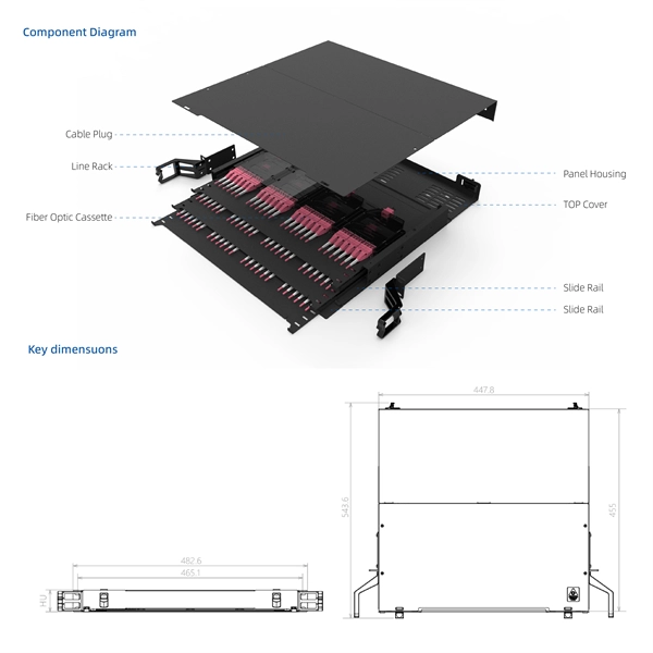
A 1U server rack measures exactly 1. 45 mm) in height and fits standard 19-inch racks. For example, a typical full-size rack cage is 42U high, while equipment is typically 1U, 2U, 3U, or 4U high. The rack unit size is based on a standard rack specification as defined in EIA -310. The Eurocard specifies a standard rack unit as the unit of height; it also defines a similar unit. U (rack unit, RU) is a unit of equipment height in a 19" rack. Important: U describes height only, but a server's real "capabilities" are also determined by chassis depth, internal layout, airflow, rails, power, and expansion (PCIe/risers, NVMe. Originally defined by the EIA-310 standard, the rack specifies a front panel width of 19 inches (482. 6 mm), allowing different hardware from various manufacturers to fit in the same enclosure. The unit calculator below can convert rack U's into cm, inches and feet. You'll get the precise, standardized dimensions of a 1U server rack unit — including height (1. 45 mm), width (19″ / 48. This three hole grouping is known as a rack unit (RU) or “U”.
[PDF]
You can access the switch through the serial console port or the Mini USB console port. Only the Mini USB console port is available if you connect both the serial console port and Mini USB console port. This chapter describes how to connect your switch to a network. In this video tutorial I show you How to configure Access Port in H3C switch, how to configure Trunk Port in H3C switch, How to All. more Hello Friends, In this video I will show you H3C Switch Configuration. On the switch, you can configure Telnet or SSH for remote access through Ethernet ports.
[PDF]

This video goes over common types of connectors, their respective adapters, and how to properly connect and disconnect them. more Are you interested in seeing how fiber optic connectors get. Unplugging a fiber jack, also known as a fiber optic connector, is a delicate process that requires attention to detail and proper handling to ensure the integrity of the fiber optic cables and connectors. Fiber optics are used in a variety of applications, including telecommunications, internet. If you're wondering how to remove fiber optic cable from connectors, there are a few different ways to do it. You need to know which connector is the correct one for the cable and what kind of wire it's made of. You can also use shears or wire cutters to cut through the connector. This article. Fiber optic connectors are essential components in fiber optic networks, providing a reliable connection between cables and equipment. Removing these connectors requires care to avoid damaging the delicate fibers or the connector itself. To connect a fiber optic cable to SFP optical module, first ensure the SFP is fully inserted into the network port until it "clicks", then remove the dust caps from both the SFP and the LC fiber optic connector.
[PDF]

The management interface is located above the console port on the rear panel of the Mobility Access Switch. It is labeled as mgmt. The management port is a dedicated interface for out-of-band management purpose. When connecting a PC to the Ethernet management port, you must first assign an IP address. Whereas, a Console Port is a serial interface used for direct, local device access via a console cable, typically during initial setup or troubleshooting. This interface is specifically available for the management of the system and cannot be. Right now, it won't, because no device points to the switch's Mgmt. IP as a gateway, but all one would need to do is connect to a port on the Mgmt. VLAN and manually enter the switch IP as a gateway and then you'd be able to route between all four subnets. The solution is to remove the VLAN. You can access and manage the switch using the GUI (Graphical User Interface, also called web interface in this text) or using the CLI (Command Line Interface). There are equivalent functions in the web interface and the command line interface, while web configuration is easier and more visual than. This topic describes how to configure the management port. It includes the following information: You connect the management port to an Ethernet switch or router that is part of your internal local area network (LAN) and that can connect to your network management infrastructure.
[PDF]

Home and business fiber optics projects typically range from a few hundred to several thousand dollars, depending on run length, fiber type, and labor needs. The main cost drivers are materials, installation time, and environmental factors that affect trenching, conduit, and terminations. Commercial building installations with 100-200 network drops generally range from $15,000 to $30,000. Single-mode fiber costs less per foot than multimode fiber, but it requires more. What is Fiber optic network design? Fiber optic network design involves the planning, routing, and drafting of Fiber cable layouts to support high-speed data transmission. It includes detailed mapping of backbone, distribution, and drop connections for FTTH, FTTP, FTTx, and enterprise networks. Fiber optic network design refers to the specialized processes leading to a successful installation and operation of a fiber optic network. It includes first determining the type of communication system (s) which will be carried over the network, the geographic layout (premises, campus, outside. According to ResearchAndMarkets, the global market for fiber optics was estimated at $5. 8 billion in 2022 and is expected to reach $11. This is the dominant broadband access technology across half of OECD countries today. The price landscape varies from basic drop cables to enterprise backbone runs, with per foot and per reel pricing common in estimates. This guide presents cost ranges.
[PDF]
Available in five IT load configurations from 18 to 90kW, this modular data center supports fast rollout, high reliability, and seamless integration—ideal for large-scale deployments and future-ready data center solutions. Delta InfraSuite is a new generation, highly integrated modular datacenter solution. It uses racks as the datacenter carrier and fully integrates all sub-systems including UPSs, cooling, power distribution, lightning protection, fire control (optional), wiring, airflow management, intelligent. The Delta Xubus Node is a prefabricated modular data center designed to meet this need—offering an offsite-built, plug-and-play solution that combines power distribution, cooling systems, and critical IT infrastructure into a factory-tested unit. As a global leader in thermal and power management solutions, Delta has further strengthened its leading position in data center infrastructure with a.
[PDF]

This complete guide explores everything you need to know about ODFs — from their structure, types, and key components, to installation best practices and modern design trends. Whether you're building a central office, data center, or FTTx distribution network, understanding the right ODF. An Optical Distribution Frame (ODF) is the central hub for fiber splicing, termination, patching, and cable protection in modern optical networks. This guide demystifies ODF, exploring their design, core functions, types, and how they. Fiber distribution hardware manages each fiber and connection point that is associated with active electronics. Why do operators, designers, and installers use additional fiber optic hardware racks for cable and fiber management? The active electronics are the most expensive part of the. A bad ODF can cause signal loss, slow repairs, and network outages. Let's talk about ODFs the way engineers and buyers need — with facts, clear advice, and practical steps. It's where. An ODF is a central hub in fiber optic networks, crucial for managing and organizing the variety of fiber-optic cables and connections entering a facility such as a telco central office (CO). Key points An optical distribution frame (ODF) is a central hub in fiber optic networks, crucial for.
[PDF]
In this paper, we present this new method of building OMS-OOCCN or its model. System design Our method applies three key information processing techniques such as geographic information system (GIS), simulation and expert system (ES) ones. We developed a specialized Geographic Information System for an internet service provider operating a fiber-optic network across multiple neighboring locations. Really, they are also the most important techniques for. Location Data (C. Summary of descriptive data (C. Manage Fiber Optics Network (maintenance &operation) (C. Final. A leading telecom infrastructure provider responsible for planning, deploying, and maintaining optical fibre cable (OFC) networks to expand digital connectivity across urban and rural regions. The client needed a reliable and accurate system to document, monitor, and manage thousands of kilometers.
[PDF]

We are offering a comprehensive, fabrication-ready CAD file for a standard electrical distribution box. This isn't just a simple layout; it's a detailed mechanical drawing intended for electrical engineers, panel builders, and fabricators. High-performing, reliable product solutions that transmit data, power and signal in cars, planes, power grids, appliances, electro. Discover all CAD files of the "Power Distribution Boxes" category from Supplier-Certified Catalogs ✅ SOLIDWORKS, Inventor, Creo, CATIA, Solid Edge, autoCAD, Revit. The CAD files and renderings posted to this website are created, uploaded and managed by third-party community members. This content and associated text is in no way sponsored by or affiliated with any company, organization, or real-world good that it may purport to portray. It is running model of. Development of a distribution box for a meter. Download CAD block in DWG. 22 KB). Disassembly of a distribution box of a Perkins engine Already Subscribed? Free download Distribution box in DWG format or CAD block. This component, also known as a breaker panel or consumer unit, is the central nervous system for power management in any residential, commercial, or industrial setting. We design and manufacture a range of electrical products for the distribution, protection, control and management of electrical systems in low voltage environments. We help our customers to design and build their own.
[PDF]


